| | | Opening ThemeEnding Theme Recent News![the case study of vanitas vol 2 Winter 2022 Simulcast List [Update 2/6]](https://cdn.myanimelist.net/r/50x78/s/common/uploaded_files/1640812873-9d25153d273bc8855c0f104e6899a45b.jpeg?s=1f5ee44f237fd6b06a35433dd13654b6) Winter 2022 Simulcast List [Update 2/6] In this thread, you'll find a comprehensive list of television anime acquired for simulcast release during the Winter 2022 season. Anime series licensed for hom... read more Dec 29, 2021 1:21 PM by Snow | Discuss (43 comments)  PV Collection for Dec 20 - 26 Here is a collection of promotional videos (PV), television ads (CM), and trailers for the last week. This thread excludes videos that have already been featured in ... read more Dec 27, 2021 3:22 AM by Snow | Discuss (0 comments) Recent Forum Discussion | | )
- Jan 18, 2022 | 52 replies | by
Sep 5, 4:43 AM | | | Poll: )
- Apr 1, 2022 | 86 replies | by
Sep 1, 6:21 PM | | | Poll: )
- Mar 25, 2022 | 74 replies | by
Jun 6, 11:50 PM | | | Poll: )
- Mar 11, 2022 | 65 replies | by
Jun 6, 2:28 AM | | | Poll: )
- Jan 14, 2022 | 86 replies | by
Jun 1, 5:30 AM |
More Top Anime- 1 Sousou no Frieren
- 2 Fullmetal Alchemist: Brotherhood
- 3 Steins;Gate
- 5 Shingeki no Kyojin Season 3 Part 2
More Top Airing Anime- 1 Monogatari Series: Off & Monster Season
- 2 One Piece
- 3 "Oshi no Ko" 2nd Season
- 4 Doupo Cangqiong: Nian Fan
- 5 Tunshi Xingkong 4th Season
More Most Popular Characters- 1 Lamperouge, Lelouch
- 3 Monkey D., Luffy
- 4 Lawliet, L
- 5 Roronoa, Zoro
 - Cómics y Novelas Gráficas
Lo sentimos; hubo un problema. Descarga la app de Kindle gratis y comienza a leer libros Kindle al instante desde tu smartphone, tablet o computadora, sin necesidad de ningún dispositivo Kindle . Lee al instante desde tu navegador con Kindle para la web. Usando la cámara de tu celular escanea el siguiente código y descarga la aplicación Kindle.  Imagen no disponible - Para ver la descarga de este video Flash Player
- VISTA EN 360º
Seguir al autor The Case Study of Vanitas, Vol. 2 (Volume 2) (The Case Study of Vanitas, 2) Tapa blanda – 23 Mayo 2017- Parte de la serie The Case Study of Vanitas
- Número de páginas 274 páginas
- Idioma Inglés
- Editorial Yen Press
- Fecha de publicación 23 Mayo 2017
- Curso 11 and up
- Edad de lectura A partir de 16 años
- Dimensiones 5 x 0.75 x 7.45 pulgadas
- ISBN-10 0316471682
- ISBN-13 978-0316471688
- Ver todos los detalles
Los clientes que compraron este producto también compraron Opiniones editorialesBiografía del autor, detalles del producto. - Editorial : Yen Press; Illustrated edición (23 Mayo 2017)
- Idioma : Inglés
- Tapa blanda : 274 páginas
- ISBN-10 : 0316471682
- ISBN-13 : 978-0316471688
- Edad de lectura : A partir de 16 años
- Curso : 11 and up
- Dimensiones : 5 x 0.75 x 7.45 pulgadas
- nº1,986 en Fantasía Manga (Libros)
Videos de este producto Haz clic para reproducir el vídeo  Opinión de cliente: Came in poor condition Sobre el autorJun mochizuki. Descubre más de los libros del autor, mira autores similares, lee blogs del autor y más Opiniones de clientes- 5 estrellas 4 estrellas 3 estrellas 2 estrellas 1 estrella 5 estrellas 89% 7% 3% 0% 1% 89%
- 5 estrellas 4 estrellas 3 estrellas 2 estrellas 1 estrella 4 estrellas 89% 7% 3% 0% 1% 7%
- 5 estrellas 4 estrellas 3 estrellas 2 estrellas 1 estrella 3 estrellas 89% 7% 3% 0% 1% 3%
- 5 estrellas 4 estrellas 3 estrellas 2 estrellas 1 estrella 2 estrellas 89% 7% 3% 0% 1% 0%
- 5 estrellas 4 estrellas 3 estrellas 2 estrellas 1 estrella 1 estrella 89% 7% 3% 0% 1% 1%
Las opiniones de clientes, incluidas las valoraciones de productos ayudan a que los clientes conozcan más acerca del producto y decidan si es el producto adecuado para ellos. Para calcular la valoración global y el desglose porcentual por estrella, no utilizamos un promedio simple. En cambio, nuestro sistema considera cosas como la actualidad de la opinión y si el revisor compró el producto en Amazon. También analiza las opiniones para verificar la confiabilidad. Opiniones con imágenes Very thick! - Ordenar opiniones por Opiniones principales Más recientes Opiniones principales
Opiniones destacadas de los Estados UnidosHa surgido un problema al filtrar las opiniones justo en este momento. vuelva a intentarlo en otro momento..  Opiniones más destacadas de otros países - Trabaja en Amazon
- Acerca de Amazon
- Relaciones con los Inversionistas
- Dispositivos Amazon
- Amazon Science
- Vender productos en Amazon
- Vende en Amazon Business
- Vender aplicaciones en Amazon
- Programa de Afiliados
- Anuncia tus Productos
- Publica tu Libro en Kindle
- Habilita un Amazon Hub
- › Ver más Gana Dinero con Nosotros
- Compra con Puntos
- Recarga tu Saldo
- Conversor de divisas de Amazon
- Amazon y el COVID-19
- Tus Pedidos
- Tarifas de Envío y Políticas
- Devoluciones y Reemplazos
- Administrar Contenido y Dispositivos
- Condiciones de uso
- Aviso de privacidad
- Aviso de Privacidad de Datos de Salud del Consumidor
- Tus opciones de privacidad de los anuncios
  The Case Study of Vanitas 2The Case Study of Vanitas 2 is the second volume of Jun Mochizuki 's The Case Study of Vanitas .  - 1 Front Cover
- 2 Publisher's Summary
- 3 Inner Cover
- 4 Table of Contents
- 6 Extra Pages
- 7 Additional Content
- 8 Author's Note
- 9 Bonus Content
- 10 Navigation
Front Cover [ ]The central character is Noé Archiviste who stands center-frame with his left hand open and lifting slightly up, and his right arm clenched into a fist and resting resolutely at his side. His head is turned to the right and slightly downward, his glowing red eyes half-lidded and bared fangs dripping with blood, which stains his collar to his chest to his torso to his right leg. Behind him in the background is a gilded portrait with a round shape, the sides made out of a pair of spinal cords, and decorated with gilded lilies, gears, and a blank journal and quill. Within the portrait, framed on either side by violet curtains, is Noé's Teacher , face concealed and his silhouette looking to be made of the dark blue night sky filled with stars. The Teacher's arms stretch out of the frame and almost cradle Noé's head on either side. Behind everything among a stark white background are outlines of golden gears on either side of the portrait frame. Publisher's Summary [ ]Now installed at a hotel in Paris with the help of Count Orlok, Noé and Vanitas take their awkward partnership on the road... to a Vampire masquerade ball! The order of the evening may be small talk and hobnobbing with fellow guests, but the mystery of the curse-bearers is never far behind. Intrigue swirls as quickly as the dancers twirl, a blue moon ascends over the guests... and all hell breaks loose! Inner Cover [ ] The central character is Jeanne bathed in a soft golden light, making her appear almost ethereal under its glow. She is wearing her dress from when she attends the bal masqué, and is clutching her headpiece's transparent veil in her hands, pressing it to her face as she makes a half-lidded, reserved expression. She is surrounded on all sides by lilies, some blooming and some still buds, and a small group of stars falls above her head. The outlines of golden gears are overlaid over her image. Table of Contents [ ] • Mémoire 5: Archiviste — Fangs That Reveal Blood • Mémoire 6: Altus — Other World • Mémoire 7: Bal Masqué — Night of Sneering Masks • Mémoire 8: Louis — Sinking in a Pool of Blood • Mémoire 9: Réminiscence — Friends • Mémoire 10: Salvatio — Uncertainty Murr at Galerie Valentine  Back when Noé grabbed Vanitas and jumped across the rooftops to pursue the Ninefold Murderer, Murr was left behind once again. As a result, he returned to Orlok's office, where he currently sits seething in place. Nox and Manet discover him and go pale in shock. Orlok, aura menacing as he approaches, finds the two of them trying and failing to subdue Murr, and they both pale as they see him. Manet has the furious and scratching cat in his arms and Nox apologizes and rushes to try and get Murr outside. However Orlok, expression as dark and serious as ever, declares they're not treating him right. He pulls out a cat toy. Orlok starts to play with Murr, swishing the toy around as the now delighted cat jumps and follows his every move. Manet is amazed at Orlok's skills, and Nox offers Murr a bowl of milk to drink. The three of them are now great friends. Characters' ages  A question is posed — what are the characters' ages? Down the line, each of them answer. Vanitas is eighteen. Noé, holding Murr in his arms, answers that he's nineteen. Dominique leans in next to him and adds on that she's twenty. When the question comes to Dante, he answers with eighteen then asks why. Immediately everyone else who answered reels back in utter shock. Noé is baffled by the idea that Dante is younger than him, and Dominique leans back to look him up and down with a new perspective. Vanitas laughs mockingly that Dante despite how he looks is in fact his same age. Dante, irritated, sarcastically apologizes for looking old. A note at the bottom from Mochizuki, saying that though she believes herself to be drawing Dante at the correct age, everyone whom she tells is age to is startled to find out. Extra Pages [ ] Additional Content [ ] Author's Note [ ] Bonus Content [ ] Navigation [ ] | - - t | | | | •
• •
• •
•
• • • • • •
• • •
• • • • • • • • •
•
•
•
• • • •
• • •
• • • • • • • • • • | | | | | • • • • • • • | | | | Terminology | • • • • • •
• • • •
• • •
•
• • • | | | | Locations | • • • • • • • • • | | | | | • • • • • • • • • • | | | | Omake | | | | | | • • • • • • • • • • • • • • • • • • • • • • • • • | | | | | • • • • • • • | | | | | • • • | | | | | • • • • • • | | | | | • • • | | | | Other Media | | | | | Extra | • • • | | | | Author | | | - - t | | | Excursion Arc | • • • • | | | | Bal Masqué Arc | • • • • • | | | | Arc | • • • • • • • • • | | | | The Arc | • • • • • • • • • • • • • • • • • • • • • • • | | | | Amusement Park Arc | • • • • • • • • • • • • • • | | | | Miel Incident Arc | • • • • • • • • | | | | Intermissions | • • • | | | | | • • • • • • • • • • | | | | Omake | | | | | Other | • | - 2 Noé Archiviste
- 3 List of Characters (The Case Study of Vanitas)
The Case Study of Vanitas Manga OnlineThe case study of vanitas.  There once lived a vampire known as Vanitas, hated by his own kind for being born under a full blue moon, as most arise on the night of a crimson one. Afraid and alone, he created the “Book of Vanitas,” a cursed grimoire that would one day take his vengeance on all vampires; this is how the story goes, at least. Vanitas no Karte follows Noé Archiviste, a young man who is traveling aboard an airship in 19th century Paris with one goal in mind: to find the Book of Vanitas. A sudden vampire attack leads him to meet the enigmatic Vanitas, a doctor who specializes in vampires and, much to Noé’s surprise, an entirely ordinary human. The mysterious doctor has inherited both the name and the infamous text from the Vanitas of legend, using the grimoire to heal his patients. But behind his kind demeanor lies something a bit more sinister… All Chapters- The Case Study of Vanitas, Chapter 63
- The Case Study of Vanitas, Chapter 62.5
- The Case Study of Vanitas, Chapter 62
- The Case Study of Vanitas, Chapter 61.5
- The Case Study of Vanitas, Chapter 61
- The Case Study of Vanitas, Chapter 60
- The Case Study of Vanitas, Chapter 59
- The Case Study of Vanitas, Chapter 58
- The Case Study of Vanitas, Chapter 57
- The Case Study of Vanitas, Chapter 56
- The Case Study of Vanitas, Chapter 55
- The Case Study of Vanitas, Chapter 54
- The Case Study of Vanitas, Chapter 53
- The Case Study of Vanitas, Chapter 52
- The Case Study of Vanitas, Chapter 51.5
- The Case Study of Vanitas, Chapter 51
- The Case Study of Vanitas, Chapter 50
- The Case Study of Vanitas, Chapter 49
- The Case Study of Vanitas, Chapter 48
- The Case Study of Vanitas, Chapter 47
- The Case Study of Vanitas, Chapter 46
- The Case Study of Vanitas, Chapter 45
- The Case Study of Vanitas, Chapter 44
- The Case Study of Vanitas, Chapter 43
- The Case Study of Vanitas, Chapter 42
- The Case Study of Vanitas, Chapter 41
- The Case Study of Vanitas, Chapter 40
- The Case Study of Vanitas, Chapter 39
- The Case Study of Vanitas, Chapter 38
- The Case Study of Vanitas, Chapter 37
- The Case Study of Vanitas, Chapter 36
- The Case Study of Vanitas, Chapter 35
- The Case Study of Vanitas, Chapter 34
- The Case Study of Vanitas, Chapter 33
- The Case Study of Vanitas, Chapter 32
- The Case Study of Vanitas, Chapter 31
- The Case Study of Vanitas, Chapter 30
- The Case Study of Vanitas, Chapter 29
- The Case Study of Vanitas, Chapter 28
- The Case Study of Vanitas, Chapter 27
- The Case Study of Vanitas, Chapter 26
- The Case Study of Vanitas, Chapter 25
- The Case Study of Vanitas, Chapter 24
- The Case Study of Vanitas, Chapter 23
- The Case Study of Vanitas, Chapter 22
- The Case Study of Vanitas, Chapter 21
- The Case Study of Vanitas, Chapter 20
- The Case Study of Vanitas, Chapter 19
- The Case Study of Vanitas, Chapter 18
- The Case Study of Vanitas, Chapter 17
- The Case Study of Vanitas, Chapter 16
- The Case Study of Vanitas, Chapter 15
- The Case Study of Vanitas, Chapter 14
- The Case Study of Vanitas, Chapter 13
- The Case Study of Vanitas, Chapter 12
- The Case Study of Vanitas, Chapter 11
- The Case Study of Vanitas, Chapter 10
- The Case Study of Vanitas, Chapter 9
- The Case Study of Vanitas, Chapter 8
- The Case Study of Vanitas, Chapter 7
- The Case Study of Vanitas, Chapter 6
- The Case Study of Vanitas, Chapter 5
- The Case Study of Vanitas, Chapter 4
- The Case Study of Vanitas, Chapter 3
- The Case Study of Vanitas, Chapter 2
- The Case Study of Vanitas, Chapter 1
Block Volume and Shape: Comparison of Calculation Methods and Investigation of Possible Relationships- Original Paper
- Open access
- Published: 28 September 2024
Cite this articleYou have full access to this open access article  - Battista Taboni ORCID: orcid.org/0000-0001-6166-3244 1 ,
- Anna Maria Ferrero 1 &
- Gessica Umili 1
In dealing with rockfall risk mitigation, a proper assessment of the phenomenon is the key to correctly and precisely managing its possible consequences. In doing so, numerical simulations are an unavoidable step of the assessment process. The proper description of the slope and the falling rock is paramount. Thus, it is highly relevant to accurately assess block size and shape. Block size directly defines the kinetic energy involved in the phenomenon, whilst shape directly influences its trajectory. Tools to properly assess both block size and shape are available, either in analytical form or relying upon Discrete Fracture Network (DFN) models. However, at present, no concrete demonstration of the equivalence of these two methods is provided in the literature. Moreover, block size and shape are always treated separately, while it is likely that a relationship of some sort exists between the two as they derive from the same features of the rock mass (i.e., the 3D geometry of its discontinuities). This paper presents a comprehensive study concerning (1) the comparison between DFN and analytical approaches and (2) the existence and quantification of a shape–size correlation. A modeling campaign consisting of 20 different geometrical structures is performed with both methods, with the aim of obtaining In Situ Block Size Distributions and Shape Distributions. Although the DFN and the analytical approach have different advantages and disadvantages, they have proved to be comparable in terms of results. Both methods identify the existence of a correlation between shape and size of the blocks: the shape distribution changes with reference to block size. This result points out the importance of implementing shape distribution in rockfall numerical simulations. Finally, a suitable case study from the literature has been selected to test the applicability and usefulness of the new findings for the design of rockfall barriers. In situ block size distribution assessment through different methods. Block shape assessment and shape distribution evaluation. Investigation of relationships between block size and shape. Application to rock fall hazard assessment. Avoid common mistakes on your manuscript. 1 IntroductionIn dealing with rockfall risk mitigation, a proper assessment of the phenomenon is key for the correct and precise management of its possible consequences. In doing so, numerical simulations are an unavoidable step of the assessment process: in fact, rockfall hazard assessment involves the statistical analysis of the outputs of a large number of simulations to evaluate, for instance, the variability of the possible runout paths, and consequently to quantify the energies involved (Volkwein et al. 2011 ). The accuracy of numerical simulations is directly influenced by the accuracy and reliability of the model they are based upon. Therefore, the proper description of the slope and the falling rock are paramount. Focusing exclusively on the rock mass, two of the most influential features, in terms of influence on the propagation of a rockfall event, are block size and shape (Pfeiffer and Bowen 1989 ). Block size directly defines the kinetic energy involved in the propagation phase of the phenomenon. It is generally assumed to be one of the most relevant parameters to be assessed and quantified in rockfall hazard analysis. In fact, traditional design methods for protection works are commonly referred to as energy-based (Wyllie 2015 ). Issues arise from the fact that block size suffers from natural variability as a consequence of the natural variability of the joint spacing and orientation within a given rock mass. Therefore, a single deterministic block size value cannot satisfy the high accuracy and reliability requirements of a proper hazard assessment. To solve this issue, which is not exclusively related to rockfall modeling, but rather to the general description of the geometric features of a rock mass, the concept of In-situ Block Size Distribution (IBSD) was introduced (Wang et al. 1991 , 1993 ; Lu and Latham 1999 ; Stavropoulou 2014 ; Umili et al. 2023 ). This approach allowed to step away from single deterministic values, moving towards a fully probabilistic description of block size, where the variable is presented as a cumulative frequency distribution. Such a distribution can be obtained by means of analytical equations, such as the original definition of IBSD intended: a good overview of the available empirical relations to quantify block volume is presented by Koulibaly et al. ( 2023 ). The IBSD can also be assessed by employing a discrete fracture network (DFN) to construct a numerical model of a jointed rock mass: DFNs, as introduced by Baecher ( 1983 ), Andersson et al. ( 1984 ), and Dershowitz and Einstein ( 1988 ), are an intuitive and very powerful tool to assess the geometrical features of a rock mass, directly simulating the discontinuities within a rock volume. An IBSD can be either employed to quantitatively justify the choice of a reference block size value or directly as input for numerical simulations; this means that the IBSD approach can still be employed in the conventional and traditional design approaches while also allowing for more sophisticated techniques to be used (Taboni et al. 2023 ). Block shape is a direct consequence of the geometric characteristics of the rock mass, similarly to block size (Mauldon 1994 ). Shape also plays a significant role, as it directly influences the geometric side of the propagation phase of a rockfall event (i.e., the trajectory of the falling block) and its randomness (Kobayashi et al. 1990 ). For this reason, in recent years, the scientific literature has produced several works assessing the significance of block shape (Torsello et al. 2021 ; Caviezel et al. 2021 ; Umili et al 2023 ) and the role of proper shape integration within numerical simulations (Bourrier and Acary 2022 ). Moreover, nowadays, rockfall simulation software capable of integrating block shapes is common, although mainly limited to 3D simulations and with different levels of accuracy and complexity (Pfeifer and Bowen 1989 ; Dorren 2016 ; Toe et al. 2018 ; Leine et al. 2014 , 2021 ; Noël et al. 2016 , 2021 ). Outside of the context of run-out numerical simulations, it should be noted how shape also influences the interaction between the falling block and existing passive protection works, such as flexible barriers, along its path (Yu et al. 2021 ). Given that the natural variability of rock mass geometric properties influences block size as well as block shape, a tool to describe block shape variability quantitatively is required. Kalenchuk et al. ( 2006 , 2008 ), while analyzing block shapes derived from both DFN derived from real case studies and purely synthetic DFN models, found that the actual shapes of the observed blocks can be plotted on a triangular shape classification diagram of their design. An application of this approach is provided by Buyer et al. ( 2020 ) and Kong et al. ( 2021 ). The same results were also found by Feng et al. ( 2011 ). Following a similar approach, Umili et al. ( 2023 ) expanded upon this and introduced the Shape Distribution (SD) in the context of rockfall problems; such distribution describes the relative abundance of each shape type with reference to Palmstrom’s classification of block shapes (Palmstrom 2001 ): the intent was to provide an easy-to-reproduce analytical methodology, based upon a simplification of the actual geometry of the problem. In fact, the blocks are assumed to be orthogonal prisms, i.e., all sides are normal or very close to normal with respect to each other. Under this assumption, the distance between the opposite faces of the prism, namely the spacing between planes belonging to the same discontinuity set, corresponds to the edge length. Therefore, the spacing distributions of the three joint sets also describe the prism edges. The shape classification selected to visualize the distribution is actually irrelevant, as the methodology works in any case. Thus, it can be seen that it is possible to derive a relative frequency distribution both from DFN models and analytical methods. It should be kept in mind that DFN models require the assessment of the Representative Elementary Volume (REV) to model any real case properly (Zhou et al. 2022 ; Huang et al. 2024 ). Such a distribution can be used to define a reference shape for numerical simulations (i.e., the most frequent one) if the distribution features one clearly dominant shape type. Alternatively, one can perform as many sets of numerical simulations as the considered shape classes and weight the results based on their relative frequency. Such an approach is presented by Taboni et al. ( 2023 ), providing also a practical application. Thus, it is clear that tools to assess both block size and shape properly are available, either in analytical form or relying upon DFN models. Theoretically, both methods should yield similar or very similar results, given the same input data. In practice, to the best of the authors' knowledge, no concrete demonstration of this fact is provided in the literature. It also appears quite evident that relying on DFNs is significantly more common than employing analytical approaches when dealing with rock mass characterization and instability, independently of the scale of the phenomena (Bhusan et al. 2020 ; Wang and Cai 2020 ; Zhang et al. 2021 ; Singh et al. 2022 ; Fan et al. 2023 ;). Moreover, the two block features, namely size and shape, are always treated separately for the sake of simplicity. In reality, though, it is likely that a relationship of some sort exists between the two features, as they both depend on the same geometrical parameters (i.e., spacing and orientation of joints). As a matter of fact, both Kalenchuk et al. ( 2006 , 2008 ) and, consequently, Umili et al. ( 2023 ) pointed out that when plotting the distribution of shapes with regard to the corresponding size of each plotted block, a trend is visible: the larger the volume, the higher the likelihood of an equidimensional shape. In this paper, the authors present a comprehensive study concerning (1) the comparison between DFN and analytical approaches, highlighting the similarity of the results, methodological differences, and advantages or limitations; (2) the existence and quantification of a shape–size correlation. A modeling campaign consisting of 20 different geometrical structures is performed with both methods, with the aim of obtaining IBSDs and SDs. Although the DFN and the analytical approach have different advantages and disadvantages, they have proved to be comparable in terms of results. Finally, a suitable case study from the literature has been selected to test the applicability and usefulness of the new findings for the design of rockfall barriers. 2 Materials and Methods2.1 block volume assessment. The DFN approach provides the three-dimensional description of a rock mass discrete features. In fact, the geometrical structure of a rock mass can be modeled by employing DFN software: a defined volume is assumed as the box containing the rock mass. The input discontinuity sets, along with their geometrical features (i.e., orientation and spacing), control the number, size, and shape of the blocks constituting the model. Theoretically, an equivalent result can be obtained through an analytical approach based on the same input variables: in this case, however, the model is not explicitly or graphically created and, therefore, is not visible in a defined space; this method provides only a list of geometrical features, not associated with specific coordinates in the space. In both cases, the natural variability of the geometrical features in the rock mass can be modeled by associating frequency distributions to the orientation and spacing input data of the main discontinuity sets. Sections 2.1.1 and 2.1.2 contain a detailed explanation of both methods. 2.1.1 DFN-Based Method for Volume AssessmentA DFN creates a 3D box representing the intact rock matrix and, through specific commands, cuts it into blocks by interrupting its continuity along planes. A discontinuity set in the rock mass is modeled as a group of planes, by inputting the mean orientation, usually expressed by dip (Ψ) and dip direction (α) and their variability (σ Ψ , σ α ), the mean spacing (μ), and its variability (σ). In the research work presented here, the authors used 3DEC (ITASCA 2007 ) as a DFN: three perpendicular discontinuity sets were input to create regular blocks of six faces each. The choice of not assigning a variability to the orientation, combined with the adoption of fully persistent planes, was made to focus the attention on the effect of the variability of the spacing only. In this regard, spacing of the three sets was set to vary both in terms of μ and σ. 3DEC’s manual states that the input σ is used to assign a random deviation for each cut, generated by a call to a random number generator. This fact corresponds to the adoption of a Normal PDF. The aim of utilizing a DFN in this work is to create the IBSD under specific input conditions. However, since the modeled volume is finite, the ratio between block volumes and model volume influences the representativeness of the results. In other words, it is of fundamental importance to find the REV. With reference to jointed rock masses, the REV can be defined as the volume of investigated rock containing enough discontinuities and inhomogeneities so that the global average value is consistent for repeated measurements (Esmaieli et al. 2010 ). The value of REV for a given case can be easily assessed with a diagram such as the one proposed by Hudson and Harrison ( 1997 ), where a variable is plotted against the reference volume in order to identify the REV size. Therefore, the first series of experiments were designed to model five rock masses, each affected by the presence of three perpendicular discontinuity sets, characterized by five different triplets of average spacing values (μ 1 , μ 2 , μ 3 ) and null standard deviation (σ 1 = σ 2 = σ 3 = 0). Each triplet is associated with a constant expected volume E[V] and a different expected block shape. Based on the chosen E[V], a series of cubic models with increasing edge length are generated to find the REV. For each of these models, the block list is extracted to build the IBSD and calculate the average block size μ v and the corresponding block size standard deviation σ v . The theoretical IBSD for each of these models is represented by a vertical line extending from 0 to 100%, whose abscissa is equal to E[V]. The choice of REV, namely the choice of the model edge length, is based on the comparison of the obtained IBSDs with the theoretical one; moreover, other criteria consist of the analysis of the trends of μ v and σ v , to assess the minimum model edge length for which the influence of model size becomes negligible on the results. Once the REV is assessed, a further series of analyses can be carried out to assess the influence of spacing variability on the IBSD and SD. For this purpose, the same spacing triplets as in the first series of models are considered, and three increasing standard deviations are assumed. In this way, a total of 20 volume distributions will be obtained from the generated models. 2.1.2 Analytical Method for Volume AssessmentThe analytical method (AM) here tested is based on the definition of IBSD introduced by Umili et al. ( 2023 ). It adopts the equation for calculating block volume proposed by Umili et al. ( 2024 ), which has been proven to be geometrically correct where S 1 , S 2 , and S 3 are the average spacing values of the three discontinuity sets generating the block. The coefficient q is a dimensionless number that depends only on the relative orientation of the three joint sets defining the block, namely the angles between normal vectors; it can be calculated as where γ 12 is the angle between K1 and K2, and δ 3-12 is the angle between K3 and the intersection of K1 and K2. If the block is a regular prism whose angles among sets are all equal to 90°, q is equal to 1. Briefly, the analytical definition of the IBSD is based on the assumption that the spacing of a discontinuity set is a continuous random variable, which means that its CDF, denoted as F ( s ) = P ( S ≤ s ), defines the probability that a given spacing value S is less than s (Stavropoulou 2014 ). By adopting Eq. 1 and assuming that the spacing distributions of the three discontinuity sets are independent, the CDF of the block volume can be written as which represents the analytical definition of the IBSD. Under the assumption of constant q (E[ q ] = q , Var[ q ] = 0), Umili et al. ( 2023 ) demonstrate that it is possible to explicitly calculate the expected value and variance of the volume as follows: Equation ( 3 ) provides an average value of the volume, while Eq. ( 4 ) provides the variance of the volume, considering the combined effects of spacing variability, both in terms of mean and variance. To compare the results with those obtained with the DFN models, the same PDF distribution type (i.e., normal) and the same parameters (μ and σ) are adopted for randomly generating sets of spacing values, with which to calculate volume samples and build the corresponding IBSDs. It should be stressed, though, that the analytical approach is applicable as presented here only if no more than three joint sets are present; if this is not the case, a combinatory approach is suggested. In this regard, a DFN approach is more flexible. 2.2 Block Shape AssessmentFollowing a similar approach, it is possible to define a Shape Distribution (SD), with reference to a given block size distribution. This tool allows for a proper assessment of block shape within a given case study. The SD can be computed from the block features identified in a DFN model, as was done by Kalenchuk et al. ( 2006 , 2008 ); alternatively, it is possible to compute the SD by assuming that the joint sets are reciprocally orthogonal and employing their spacing frequency distributions as descriptors for edge length, as was suggested by Umili et al. ( 2023 ) and Taboni et al. ( 2023 ). To compare the results of the DFN and the AM, the same classification system and diagram were used: for its simplicity and ease of calculation, we selected Palmstrom’s classification (Palmstrom 2001 ). Such a classification defines four shape types, depending on the ratios between the length of the longest (Lo), intermediate (In), and shortest (Sh) edge of a block. The corresponding logarithmic diagram is, thus, divided into four sectors according to the following definitions: Equidimensional or compact prisms, with In/Sh < 2 and Lo/Sh < 2; Long prisms (rods), with In/Sh < 2 and Lo/Sh > 2; Long flat prisms (blades), with 2 < In/Sh < 1 + (Lo/Sh–1)^0.5; Flat prisms (slabs), In/Sh > 1 + (Lo/Sh–1)^0.5. Given that any classification system relies upon arbitrary boundaries to define its classes, it is easy to understand that an SD can present itself differently for different shape classifications. The existence of the SD, though, is independent of its representation on a diagram. 2.2.1 DFN-Based Method for Shape AssessmentFor each of the DFN models created, the list of vertices of each block, consisting of an identification number and its coordinates ( X , Y , Z ), is automatically extracted. The list is used to calculate the length of the six edges of each block. Due to the choice of three perpendicular sets, the edges with unique values are three for each block. They are then used to calculate the ratios In/Sh and Lo/Sh and plot the relative points on the shape diagram. 2.2.2 Analytical Method for Shape AssessmentBased on the same samples of spacing values used to build the IBSD with the AM, it is possible to calculate the ratios In/Sh and Lo/Sh for each block and plot the relative points on the shape diagram. 3 Calculation of the Required Data3.1 choice of input data. The choice of input data for generating the blocks is bound, on the one hand, by the need to use only three discontinuity sets to fulfill the requirements of the AM. On the other hand, it is constrained by the need to have perpendicular discontinuity sets to create regular blocks of six faces each and use the shape definition by Palmstrom ( 2001 ). Moreover, as described in Sect. 2.1.1 , the need to assess the influence of spacing variability on the IBSD and SD must be coupled with the identification of the REV for the DFN models. For these reasons, five spacing triplets (μ 1 , μ 2 , μ 3 ) representative of five different points on the shape diagram are chosen (Fig. 1 ): they will be referred to as combinations B1, B2, B3, B4, and B5 (Table 1 ). All the combinations are characterized by the same orientation of the three mutually perpendicular sets (K1, K2, K3) and by an identical expected block volume E[V] (Eq. 4 ) equal to 5 m 3 . According to the shape diagram, B1 is an equidimensional block, B2 a rod-like one, B3 a blade-like block, and B4 a slab-like one; lastly, B5 describes the common point between all shapes, identified by the intersection of the lines dividing the diagram into the different shape sectors. 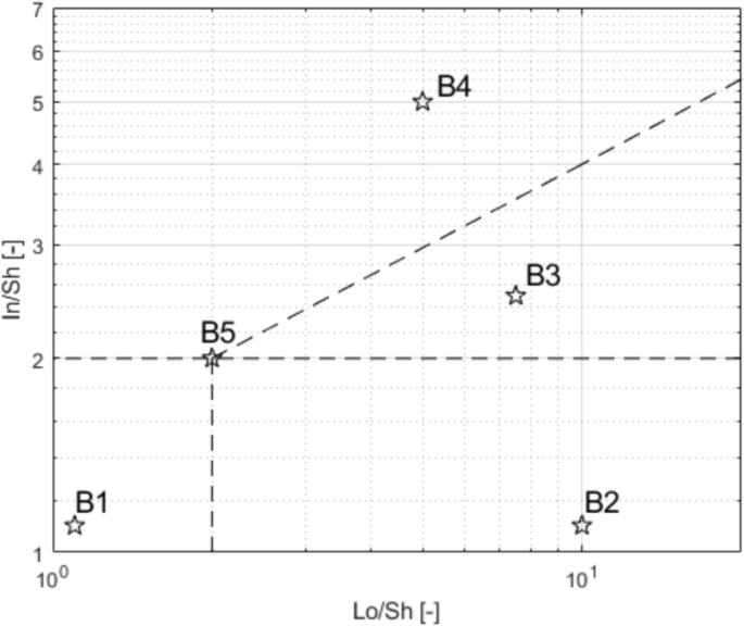 Shape diagram with the five chosen combinations B1, B2, B3, B4, and B5 For each combination, a null and three increasing σ values (0.1, 0.2, 0.5 m) are assumed. A total of 20 sets of data were created and inputted both in DFN and AM, to perform a broad comparison of the results. 3.2 REV IdentificationThe input data of the five combinations (Table 1 ) are designed to produce DFN models with the same E[V], once the REV is adopted. In light of this fact, combination B1 is used to assess the REV. B1 represents a cube whose edge length is 1.71 m. The model edge length is varied from 10 m to 45 m (Table 2 ): this means that the cubic models will theoretically contain 200 to 18225 blocks. By comparing the IBSDs obtained for the different edge lengths, it is possible to note that the curves tend to coincide with the theoretical one as the dimension increases (Fig. 2 ). The actual number of blocks in the models converges to the theoretical one with increasing edge length: from 35 m, the difference remains stable at +8% with respect to the theoretical number. Moreover, by comparing the mean μ v and standard deviation σ v of the block samples generated by 3DEC models with increasing edge length (Figure 3 ), one can observe a marked variation of both trends in correspondence with the model edge length equal to 35 m. 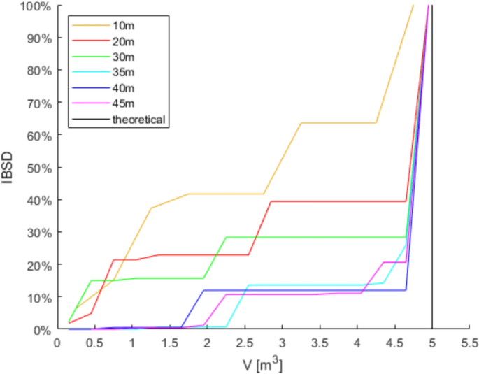 Comparison of IBSDs obtained for different values of model edge length 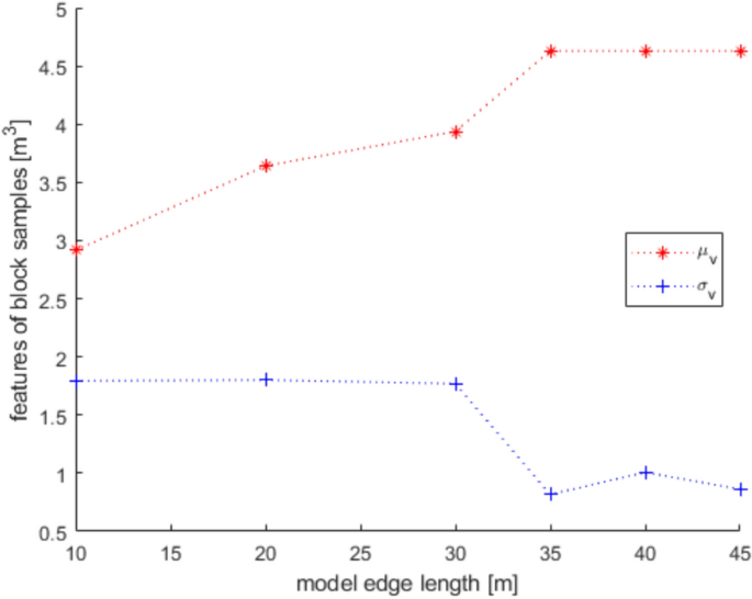 Mean μ v and standard deviation σ v of the block samples generated by 3DEC models with increasing edge length Similar considerations can be made based on fracture intensity P 32 , which is defined as the ratio of the total area of discontinuities and the volume of the rock mass considered (Zhang and Einstein 2000 ) where V is the volume of the rock mass considered; S (k) is the entire area of the kth discontinuity; m (V) is the number of discontinuities (i.e., the number of discontinuity centroids) in volume V . Values of P 32 of the DFN models, created with edge lengths from 10 to 45 m for each of the five combinations B1–B5, are calculated: Fig. 4 depicts them. Considering this estimator, too, all the trends agree and show that from 35 m edge length, values are reasonably stable as they manifest an asymptotic trend. 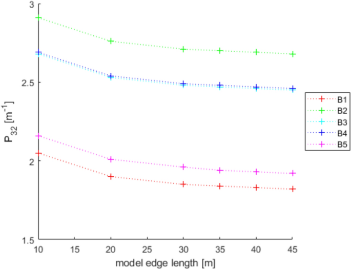 Values of P 32 calculated for the models generated by 3DEC with increasing edge length In light of these observations, a dimension of the virtual rock mass of 35 m was chosen for the following analyses as the REV. 3.3 DFN and AM Models GenerationThe DFN was used to produce the 20 designed models based on the data in Table 1 . For each model, the lists of the vertices and block volumes were extracted and processed to build the IBSD and SD. Based on the number of blocks (N) obtained for a DFN model, the corresponding AM model is generated, so that it consists of N spacing data for each discontinuity set and, consequently, N blocks. Matlab function normrnd is used to generate samples of random numbers from the Normal distribution, by inputting mean parameter (μ), standard deviation parameter (σ), and the number of values to be generated (N). 4 Results and DiscussionSince the models created through DFN and AM have the same input data, the first step for a comprehensive comparison of the results is the analysis of their raw output values. In other words, due to the fact that, in this study, block volume is the product of three spacing values, the first check must be on the ability of the two methods to produce the expected spacing values. Considering that the input data (Table 1 ) describe the theoretical and, therefore, true PDF, it is possible to describe the obtained sample by means of its average value μ* and standard deviation σ*. Defining Δ the difference between the coefficients of variation CV* and CV one can assess a normalized difference between the true PDF and the sample PDF: Δ equal to 0 represents complete equality. Figure 5 shows the Δ values obtained considering both methods: in general, values obtained with AM are closer to 0, particularly for small σ and μ greater than 1.5 m. This means that the process of values generation is rigorous, repeatable, and reliable. It is also evident that the spacing samples generated by the DFN suffer from an effect of truncation due to the actual process of subdivision of the model by means of discontinuity planes. The generated spacing samples show a more chaotic behavior of Δ, due mainly to a greater difference between the obtained σ* and the true σ. 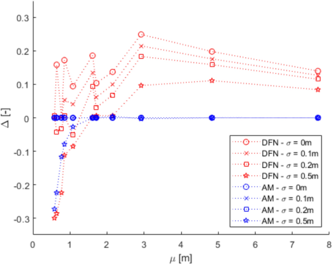 Comparison between Δ calculated with DFN and AM for different values of σ The analysis of spacing samples is essential for the investigation and assessment of volume samples. In fact, the effect of μ* and σ* deviation from μ and σ is reflected in the difference among the volume PDFs. The theoretical E[V] and Var[V] calculated with Eqs. 4 and 5 can be compared to those calculated based on block samples obtained using the DFN and AM approaches (Table 3 ). As expected and based on data reported in Fig. 5 , the PDF obtained with the AM is closer to the theoretical one than the DFN one. This fact is true regardless of the σ value. 4.1 Block SizeThe results produced by the methodologies presented in Sects. 2.2.1 and 2.2.2 for the DFN approach and the AM one, respectively, are visible in Fig. 6 : DFN derived IBSD on the left, AM calculated IBSD on the right. The results are divided according to the expected shape class of the blocks, as named in Fig. 1 . In each diagram, four IBSDs are portrayed to show the effect of increasing σ in the three parent spacing distributions. 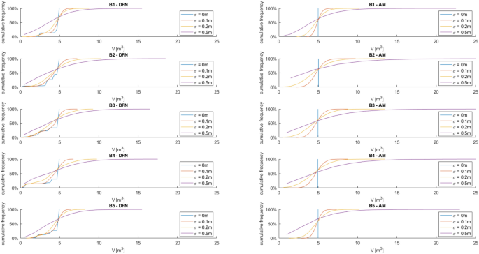 IBSDs derived from both approaches for different values of σ in the three parent spacing distributions First of all, it can easily be appreciated that the AM IBSD tends to cover a wider range of volumes. This is especially visible at high σ values (i.e., 0.5 m), and for the B2 and B3 blocks (rod- and blade-like shapes, respectively). In fact, the maximum volume computed by 3DEC in the case of B3 is roughly equal to 18 m 3 , while for the same case, the analytical solution reaches a maximum volume of 35 m 3 . This can be interpreted as a consequence of the fact that 3DEC, or any DFN software for that matter, works on a model of pre-defined volume, which has to be equal to or greater than the REV to describe the rock mass geometric properties adequately. This induces an unavoidable limitation on the size of blocks the DFN can identify, as they have to be smaller than the aforementioned pre-defined volume. Such a limitation is absent in the case of the analytic approach, which, on the contrary, can benefit from the definition of a reasonable upper volume limit: Umili et al. ( 2023 ) proposed to use V 99% , i.e., the volume corresponding to 99% probability of not being exceeded. A second feature of note, exclusively found on the DFN IBSDs, is the odd segmented curve describing low σ (i.e., 0 or 0.1 m) block size distributions. This odd curve shape is related, once again, to the pre-defined volume of the model within which the DFN computes the rock mass properties; particularly, it is a consequence of how exactly the model can be divided by the discontinuities with the assigned spacing. In other words, when the discontinuities cut the model volume to define the rock mass fracture network, the blocks along the boundaries of the model are defined in geometry (i.e., size and shape) not only by the discontinuities (i.e., their spacing and orientation) but also by the model boundaries themselves. This leads to a surplus of artificially smaller blocks, which alter the trend described by the larger blocks and, thus, the IBSD. The smaller the blocks, the more noticeable this trend: this is why the larger volume portion of the distributions is not affected. It should also be clear that the boundaries of the modeled volume can only reduce block size. The effect of this feature is clearly distinguishable only for low σ values: less than 0.1 m in our examples. The value of σ of the parent spacing distributions describes how dispersed, and therefore variable, the dataset is. In fact, as the dispersion of spacing increases, the likelihood of the appearance of smaller blocks increases as well, meaning that the presence of boundary-caused small blocks is, at least partially, masked in the appearance of the IBSD curve. The odd appearance of the IBSD curve can be removed by filtering out values below the expected one: this is conceptually fine, though, only for very small σ, as the block size value range is similarly small, and the IBSD tends towards a straight line. In all other instances, filtering out small blocks will also remove actual small blocks computed by the model. As the analytic approach does not rely on an REV or pre-defined model volume, such issues are absent from the AM-derived IBSDs. Apart from these two features, the IBSDs presented in Fig. 6 appear remarkably similar: although a complete and exact identity between the results of the two approaches is unlikely, given that they are based on different principles and assumptions, the similarity is still significant. To express this fact, Table 4 describes the values at 50%, 75%, and 95% cumulative frequency provided for each model by the two approaches. The difference between volumes at 50% of cumulative frequency calculated with AM and DFN is expressed as ΔV 50% . Similarly, ΔV 75% and ΔV 95% consider results obtained for 75% and 95% cumulative frequency, respectively. As can be seen, these selected frequencies along the IBSDs yield very close results between the two methods. The difference can be quantified considering, for all the five shapes (B1–B5), the same σ value: by entering the relative IBSDs with the considered cumulative frequency, the corresponding volumes can be inferred and the average value calculated. The difference so calculated varies from 0.3 to 0.4 m 3 for V 50% , regardless of σ. The difference ranges between 0.2 and 0.8 m 3 for V 75% , highlighting a more significant effect of the increase of σ on the increase of the difference. The maximum difference occurs for V 95% , as can be noticed by comparing the right tails of the IBSDs: it ranges from 0.1 to 2.2 m 3 by increasing σ, confirming that the AM tends to produce wider IBSDs. This fact supports the choice of adopting V 99% (Umili et al. 2023 ) as the maximum value for truncating the IBSD. 4.2 Block ShapeSimilar to what has been done for the IBSDs, Shape Distributions (SDs) have been separated according to the five reference block shapes shown in Fig. 6 . Figures 7 , 8 , 9 , 10 , 11 portray Palmstrom’s diagrams of blocks B1–B5, showing the effect of increasing σ value (from 0 to 0.5 m) for the parent spacing distributions. 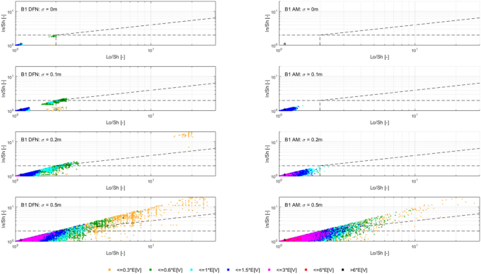 Computed SDs in the case of reference block B1 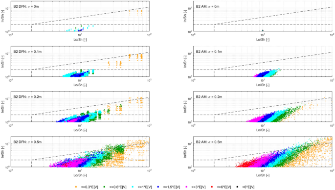 Computed SDs in the case of reference block B2 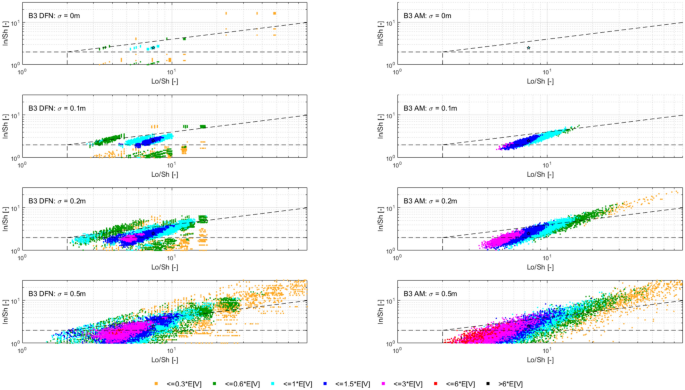 Computed SDs in the case of reference block B3 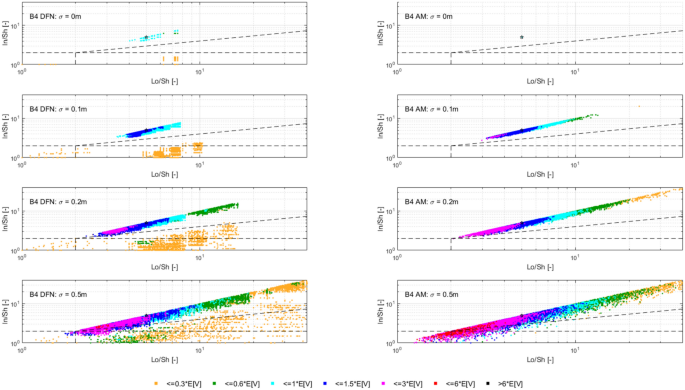 Computed SDs in the case of reference block B4 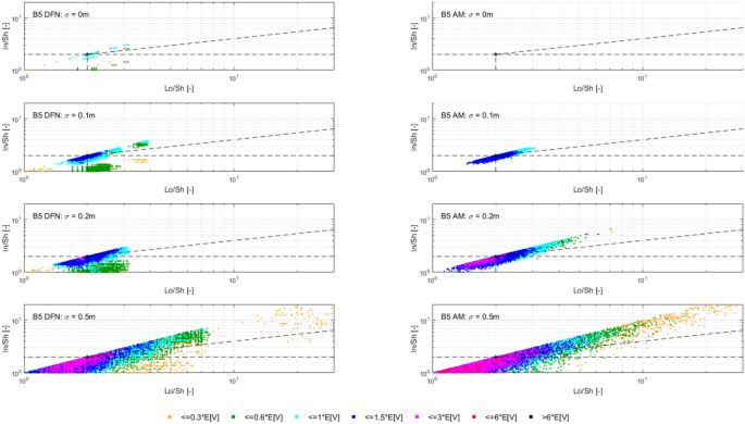 Computed SDs in the case of reference block B5 The first noteworthy feature of these figures is the fact that as σ of the spacing distributions increases, the resulting blocks are plotted in an increasingly dispersed cloud stretching towards the right side of the diagram. Moreover, just as anticipated, if we distinguish the blocks based on their size (in our case, relative to the expected block size E[V] ), it can be seen that the larger blocks (purple and red colored dots) tend to concentrate on the left side of the diagram. In the figures, this fact appears more clearly in the case of the AM-derived IBSDs, and is particularly evident in the case of block B3 (blade-like shape, Fig. 9 ). This is in part due to the issues with the way the DFN model is set up and its need for a pre-defined REV, as detailed in the previous Sect. 4 . For such reasons, the size–shape distributions (SSDs) derived from the DFN model appear less homogeneously dispersed. Moreover, even in the case of σ = 0 for the spacing distributions, when the dot representing the single value SSD is expected to correspond directly with the reference point (the star in the diagrams), this condition is satisfied by all the AM-derived distributions, except for the B1 case (equidimensional shape), whilst the DFN derived distributions always show a degree of dispersion around the reference point. Again, this is a consequence of boundary effects along the pre-defined REV required to construct the DFN model. In this regard, it is clear that the AM-derived distributions, for both size and shape, appear to yield more consistent and reliable results. These considerations regarding the effects of the DFN reliance on a pre-defined REV and boundary effects at the edges of the calculation volume can be extended to all the other cases described in Figs. 7 , 8 , 9 , 10 . In fact, by definition, a DFN analyzes only a pre-defined volume (i.e., the REV), considering it a model of the studied rock mass. Thus, the model size, although cautious and justified through quantitative means, as shown in this paper, still consists of a single, finite value. Therefore, the DFN-based approach appears intrinsically finite in nature, especially when compared to the AM, which does not require any model size but is purely based on the orientation and spacing distributions describing the joint sets. In other words, the AM describes the rock mass exclusively on a probabilistic level. Alongside Palmstrom’s diagrams, the easiest and clearest representation of an SD is a pie chart. In Figs. 12 , 13 , 14 , 15 , 16 , two sets of pie charts are presented, describing the actual SD for each of the five reference shapes with increasing σ. In Figs. 17 , 18 , 19 , 20 , 21 , a second set describing the corresponding size distribution is presented. 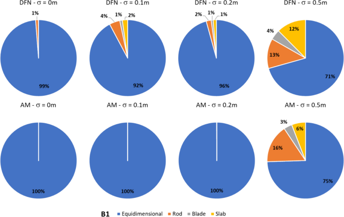 Shape distribution pie charts for the B1 reference block 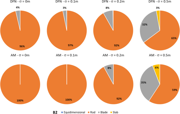 Shape distribution pie charts for the B2 reference block 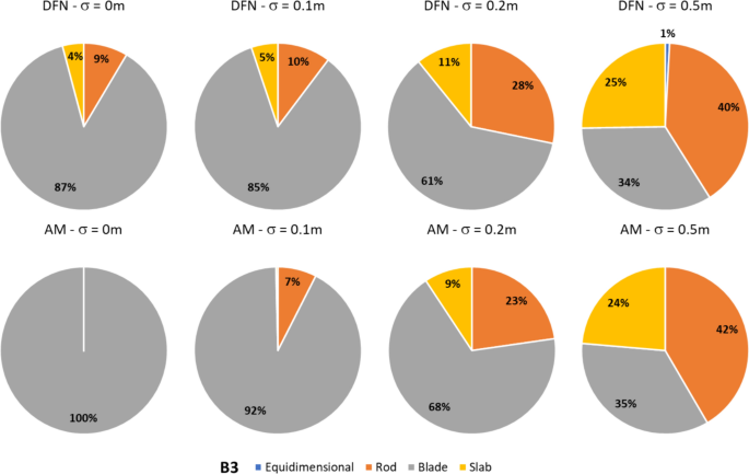 Shape distribution pie charts for the B3 reference block 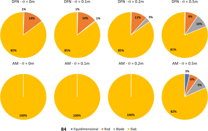 Shape distribution pie charts for the B4 reference block 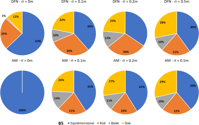 Shape distribution pie charts for the B5 reference block 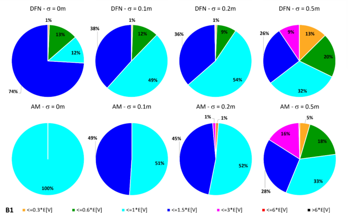 Pie charts describing block size for reference block B1 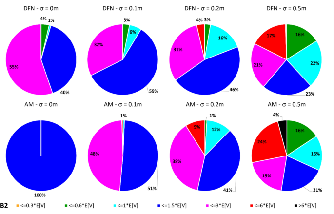 Pie charts describing block size for reference block B2 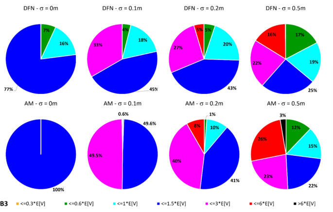 Pie charts describing block size for reference block B3 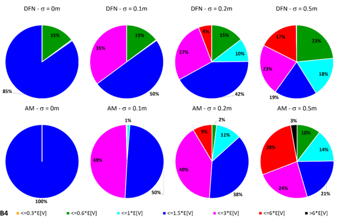 Pie charts describing block size for reference block B4 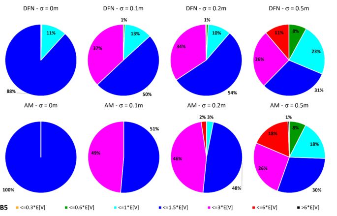 Pie charts describing block size for reference block B5 A glance at the SD pie charts shows how similar the outputs of both methodologies are for high σ values (0.2 and 0.5 m) for the parent spacing distributions: in most cases, the difference between the DFN-derived and the AM-derived SDs are within a few percentage points. The results are significantly different among the two methods for low σ values (0 and 0.1 m): in almost all cases, the AM SD all show the expected shape as dominant, whilst the DFN SD allows for other shapes to appear, amounting to up to 16% of the distributions. The only exception is reference block B3 (blade-like block), where for σ = 0.1 m the AM SD, too, shows some variability in the possible shapes. This fact is, once again, related to the issues of the deterministic approach required by the DFN to work. Major differences are also found for reference block B4 (slab-like shape), where the AM SD describes the absence of non-slab-like blocks for cases with σ = 0, 0.1 and 0.2 m, whilst the DFN-derived SD states that non-slab-like blocks amount to approximately 15% (Fig. 15 ). Considered here separately, for its specific and special nature, is reference block B5, which falls on the intersection of the shape domains within Palmstrom’s diagram. This point describes a limit condition where none of the four classes upon which the shape classification is defined are applicable. Conversely, this point can be seen as sharing features of all the four classes, without belonging to one in particular. The special nature of this point is also linked to the fact that depending on the definitions of the boundaries between the four shape classes, one and only one set of conditions identifies the point. This means that the likelihood of a block appearing with this shape is extremely low, but more importantly, no other point outside of it can be classified in the same manner. Therefore, it is an especially interesting position to visualize the SSD (Figs. 16 , 21 ). Regarding the shape frequency pie charts (Fig. 16 ), apart from the case of σ = 0 m, the two methodologies produce very similar results: most of the larger blocks tend to fall clearly within the domain of equidimensional shapes. This is evident even in the case of the DFN-derived SSD: at σ = 0.5 m, the difference is approximately 1%. Regarding the volume distribution pie charts (Fig. 21 ), the special point B5 does not exhibit special features and behaves in accordance with all the others. Looking at the second set of pie charts (Figs. 17 , 18 , 19 , 20 , 21 ), differences appear between the two methodologies. In general, the DFN-derived distributions tend to have a more significant number of blocks smaller than the expected block size ( V < 1 E [ V ]) and usually miss entirely the largest ones ( V > 6 E [ V ]). As σ of the parent spacing distributions increases, the dispersion of the size data throughout the considered classes increases, and the differences between the two methods tend to reduce. In fact, for σ = 0.5 m, the distributions are significantly close to each other, taking into account the tendency of the DFN data to have a higher count of smaller blocks. For instance, in the case of reference block B1 (equidimensional shape, Fig. 17 ), most of the computed blocks fall within 1 E [ V ] and 1.5 E [ V ], with remarkably similar percentages for both approaches: for 1 E [ V ], 32% in the case of the DFN derived data, 33% for the AM; for 1.5 E [ V ], 26% and 28%, respectively. It should be noted that the issues of the DFN model are the same discussed in the paragraph on block size (Sect. 4.2 ): boundary issues introduce artificially smaller blocks and impose an upper limit to block size. 4.3 Case StudyTo show an application of what has been introduced in the previous paragraphs regarding the block size–shape relationship, a case study has been selected. In Taboni et al. ( 2023 ), the rockfall hazard assessment of the site of Grangia Cruset (Municipality of Bellino, Province of Cuneo, Piemonte Region) is presented. Located in the westernmost portion of Varaita Valley, in the Western Italian Alps, the exposed buildings are located at the toe of a steep slope overhung by rocky peaks, which act as rockfall sources. The most recent event was registered in 2017 and involved a total volume of approximately 100 m 3 of fallen rocks, estimated by measuring the scar left on the rockface. Most of the blocks that actually reached the exposed buildings had a volume of approximately 1 m 3 , while the largest single boulder reached 6 m 3 . No data are available on the number or volume of the originally detached blocks: although no evidence of fragmentation was found, it is not impossible that during the rockfall the original blocks experienced it. Thus, as the referenced data describe the blocks measured after the event and at their stopping position, their size represents a lower bound on the initially released block sizes. Thus, the possible fragmentation of larger volumes was not considered. The authors produced a new methodology for rockfall hazard assessment, employing IBSD to describe block size and an SD for its shape; they then ran four sets of one thousand 3D simulations of block trajectories, one for each of the four shape types defined by Palmstrom (2001), and integrated the result for a global description of the problem. The SD used was referred to the entire IBSD, which may differ significantly as the volume increases, as it was shown in the previous paragraphs. Thus, as the relationship between block size and volume was not addressed in the original paper, the same case study can be used to provide a quick but reliable example of how to implement it in a real situation without increasing complexity at the point of making the methodology impractical and, thus, useless. It should be mentioned that only the AM was employed for the case study at hand. For the purpose of this study, the same IBSD and SD described in Taboni et al. ( 2023 ) are considered: they are reported in Table 5 . To properly integrate the size–shape correlation into the rockfall numerical analysis, the approach consists of filtering out the shapes of the SD belonging to rock blocks whose volumes fall out of a given interval. A reasonable interval can be derived from the existing regulations regarding passive rockfall mitigation works, which usually insist upon incrementing the reference design volume by applying a partial factor (UNI 11211 2019 ) to account for a higher effect of the acting force, namely the kinetic energy of the impacting block. For this reason, we chose to filter the SD within a range of ± 10% of the reference volume, which was estimated to be 6.5 m 3 (slightly larger than the largest block recorded on site, amounting to 6 m 3 ). To assess the effect of size–shape correlation on smaller blocks, the average registered block (1 m 3 ) was also modeled. By filtering out all the blocks that fall out of the interval, the resulting filtered SD now describes only the relative abundances of the shapes associated with blocks comparable to the reference volume; therefore, the filtered SD provides a more accurate shape sample. Finally, following the same workflow of the original paper, new global results for the 3D numerical simulations based on the filtered SDs were produced by calculating, as suggested by Taboni et al. ( 2023 ), and average weighted over the relative abundances of the four shape classes, according to the following relation: where SO is the global output; PO e , PO r , PO s , and PO b are the partial output for the equidimensional, rod-like, slab-like, and blade-like shape, respectively; e , r , s and b are the relative abundance of the equidimensional, rod-like, slab-like, and blade-like shapes within the considered SD. The Grangia Cruset case study presented by Taboni et al. ( 2023 ) has been modified and integrated to account for the shape–size correlation. The IBSD employed in the original paper has been filtered out, extracting two different portions: the one within a 10% range around the reference design value (6.5 m 3 ) and the one within a 10% range around the average recorded falling block (1 m 3 ); then, the two new SDs have been computed and new numerical simulations carried out. The slope model is exactly the same as the original paper. From here onward, the same methodology detailed in Taboni et al. ( 2023 ) has been followed to combine the contributions of each of the four shapes. Figure 22 shows the comparison between the original global SD and the new ones, focused on the two considered block sizes. 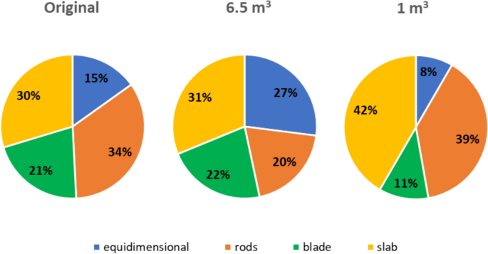 SDs for the Bellino case study: the original SD (left) (from Taboni et al. 2023 ), the SD focused on the 6.5 m 3 block (middle), and the SD focused on the 1 m 3 block (right) As it can be seen, the difference is significant: for instance, in the 6.5 m 3 case, equidimensional blocks are more relevant (+ 12%) than in the global SD, while rod-like blocks are less frequent (−14%); meanwhile, for the 1 m 3 case, equidimensional blocks are less frequent (−7%), alongside blade-like blocks (−10%), whilst slab-like blocks appear to be more prominent (+ 12%). Once again, the increase of equidimensional blocks at higher volumes, or conversely, their decrease at lower volumes, is appreciable. The effect of the new SDs on the maps produced by the 3D rockfall software Rockyfor3D (Dorren 2016 ) is difficult to appreciate based solely on the maps themselves. To quantify the difference, data regarding total kinetic energy ( E k ) have been extracted along a line, symbolizing the extent of a possible protection work. Figure 23 describes the case for the 6.5 m 3 block, while the Fig. 24 compares the E k values of the original run of simulations and the new one along that line. 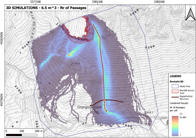 Runout model for the 6.5 m 3 case, with the most frequent path in red and the trace of a hypothetical protection work 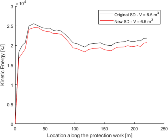 Comparison between E k of the original (black line) and new 6.5 m 3 simulations (red line) along the hypothetical protection work As can be seen, the energy involved in a rockfall event for a 6.5 m 3 block is consistently lower if the filtered SD is considered. On average, the difference is between 5 and 10% of the original value (between 1000 and 2000 kJ). Unfortunately, considering that the reference energy level of the modeled phenomenon, as stated in the original paper, is in the range of 25,000 kJ, a difference of 10% does not significantly affect the design process of any kind of protection work. A similar trend can be observed also for the bounce height. Figures 24 and 25 present the results for the 1 m 3 case. 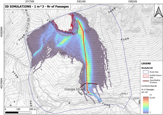 Runout model for the 1 m 3 case, with the most frequent path in red and the trace of a hypothetical protection work While in the previous case, the new set of simulations produced lower E k outputs, and the difference is between 10 and 20%, in this second instance, the new values are actually higher than the original outputs. More importantly, as the maximum energy value extracted is close to 5000 kJ, a difference of 1000 kJ signifies a skip between different commercial classes of passive protection works, such as flexible barriers. This is important, as commercial rockfall barriers are sold in pre-defined energy categories: for example, if referencing the original outputs, a 5000 kJ barrier would have been enough, while for the new results, a higher energy level is required. Usually, this means employing an 8000 kJ kit, with a significant increase in the costs. The fact that in both Figs. 24 and 26 , the new model appears very similar to the original one, simply shifted towards higher or lower energy levels, is not to be intended in any way as a feature of the approach presented here. This fact is likely due to two aspects: first and foremost, the configuration of the model (i.e., the topography and the features of the slope) is the same in both simulations; second, the case study manifests an apparent propensity to concentrate almost all the trajectories along the paths highlighted in Figs. 23 and 25 . By filtering the SD around the reference block sizes, the achieved effect is akin to extracting a precise portion of the simulated blocks from the more generalized original set of simulations. This is to say that the new results being similar to the original ones are, at least in this specific case, to be expected. 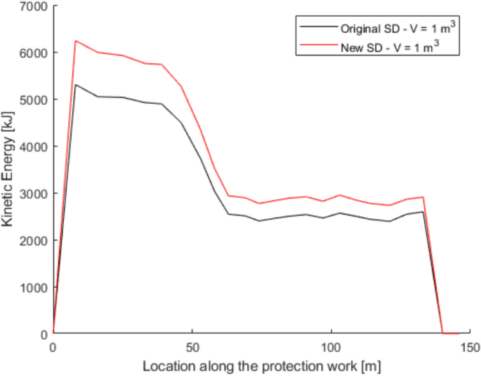 Comparison between E k of the original (black line) and new 1.0 m 3 simulations (red line) along the hypnotized protection work In general, therefore, two things can be said: first, accounting for the Shape–Size correlation could produce tangible effects on the modeling of the rockfall process; second, mass, and thus block size, seems to have a more relevant role, as for larger blocks the difference in the computed values decreases and is less relevant. 5 ConclusionsThe present work aims to compare the DFN-based and the AM-based approaches to the characterization of rock masses geometrical structure for rockfall assessment purposes. These two methods are based on different assumptions and different calculation algorithms. On the one hand, a DFN is able to generate a virtual model of the rock mass by cutting the defined box along input planes representing discontinuities. Therefore, blocks volume and side lengths are outputs of the modeling process, which requires the assessment of the REV to reduce the boundary effect. On the other hand, the proposed AM-based approach is a purely analytical method, incapable of materializing and modeling the rock mass structure, but able to calculate an IBSD based on its analytical definition, without the need to assess a REV. In conclusion, it was seen that both approaches are viable when dealing with: Block size assessment, although the DFN-based methodology has some intrinsic limitations (boundary effects on smaller blocks; upper size limit) that may hinder the accuracy of the outputs in some specific circumstances (low σ of the parent spacing distributions). The DFN-based approach has no issues in dealing with instances where more than three joint sets are identifiable, while the analytic one would require a combinatory application of the method; finally, the analytic method can handle different types of PDF without particular issues, but in the case of rock masses characterized by more than three joint sets, the approach cannot be directly employed, rendering it, in that specific case, less flexible than a DFN. Both approaches yield consistently similar and comparable results. Block shape assessment, although the basic assumptions of the DFN-based method tend to produce more clustered outputs for low σ of parent spacing distributions. Moreover, both methodologies identify the existence of a correlation between shape and size of the computed blocks, which dictates that the SD changes with reference to block size. The method to assess such correlation, as well as the way to implement it in rockfall numerical simulations or hazard assessment shown in this study, can easily be applied to both DFN-derived and AM-derived data. The case study allowed us to visualize and quantify the differences that arise when accounting for the shape–size correlation. Moreover, it demonstrated that size plays a more significant role, as in the case of larger blocks, the effects of a quite different SD are less relevant than in the case of a smaller block. It is crucial to notice that two important questions remain open. First of all, the actual appearance of an IBSD, its corresponding SD, and the correlation between the two are derived from safe and reasonable assumptions (Umili et al. 2023 ) and have yielded accurate and reliable results. Further studies are required to demonstrate such assumptions and the considerations derived from them. The information provided by modeling the geometric features of a rock mass, either by means of DFNs or analytical methods, is critical to properly constructing a model for numerical simulations of the phenomenon. Thus, it is highly important for practitioners and designers, who directly rely on the output of such simulations to acquire the needed data required to design protection structures or other mitigation measures correctly. This is also true for land planners, as numerical simulations are usually involved in hazard and risk assessment and mapping. Both block size and block shape are highly relevant parameters for rockfall, which yield direct influences on the outcomes of the simulations. This is especially significant given the now widespread presence of software based on the rigid body approach to rockfall, which are able to account for both rock size and shape. Being able to produce more precise and accurate models from a reliable input dataset, rigorously produced through a solid and repeatable methodology, is a significant improvement across all fields of application. Data availabilityData is available upon request. AbbreviationsDiscrete fracture network In situ block size distribution Shape distribution Size–shape distribution Probability density function Cumulative distribution function Coefficient of variation Representative elementary volume Fracture intensity Expected value (mean) of dip angle of a discontinuity plane Expected value (mean) of dip direction angle of a discontinuity plane Variance of dip angle Variance of dip direction angle Spacing, intended for both a deterministic value and a continuous random variable Expected value (mean) of spacing (coincident with E[S]) Variance of spacing (coincident with Var[S]) Expected value (mean) of volume Variance of volume Number of data in the spacing or volume sample Discontinuity sets Spacing of the three discontinuity sets generating the block Angles between pairs of discontinuity sets generating the block Angle between K k and the intersection of K i and K j Dimensionless number calculated based on the orientation of the three discontinuity sets generating the block Length of the longest edge of the block Length of the intermediate edge of the block Length of the shortest edge of the block Volume corresponding to n % cumulative frequency in IBSD (i.e., V 99% corresponds to 99% cumulative frequency of IBSD) Total kinetic energy of the block Andersson J, Shapiro AM, Bear J (1984) A stochastic model of a fractured rock conditioned by measured information. Water Resour Res 20(1):79–88 Article Google Scholar Baecher GB (1983) Statistical analysis of rock mass fracturing. J Int Assoc Math Geol 15(2):329–348 Bhusan R, Naik SR, Sekar V (2020) Support assessment and 3D stress analysis of large underground excavations: a case study using 3DEC. In: Billaux, Hazzard, Nelson, Schöpfer (eds) Applied numerical modeling in geomechanics, Paper: 01–05. Itasca International Inc., Minneapolis Bourrier F, Acary V (2022) Predictive capabilities of 2D and 3D block propagation models integrating block shape assessed from field experiments. Rock Mech Rock Eng 55(2):591–609. https://doi.org/10.1007/s00603-021-02696-5 Buyer A, Aichinger S, Schubert W (2020) Applying photogrammetry and semi-automated joint mapping for rock mass characterization. Eng Geol 264:105332. https://doi.org/10.1016/j.enggeo.2019.105332 Caviezel A, Ringenbach A, Demmel S, Dinneen C, Krebs N, Buhler Y, Christen M, Meyrat G, Stoffel A, Hafner E, Eberhard L, Reckenbach D, Simmler K, Mayer P, Niklaus P, Birchler T, Aebi T, Cavigelli L, Schaffner M, Rickli S, Schnetzler C, Magno M, Benini L, Bartelt P (2021) The relevance of rock shape over mass—implications for rockdall hazard assessments. Nat Commun 12:1. https://doi.org/10.1038/s41467-021-25794-y Article CAS Google Scholar Dershowitz WS, Einstein HH (1988) Characterizing rock joint geometry with joint system models. Rock Mech Rock Engng 21:21–51. https://doi.org/10.1007/BF01019674 Dorren LKA (2016) Rockyfor3D (v5.2) Revealed—transparent description of the complete 3D rockfall model. ecorisQ paper ( www.ecorisq.org ), p 32 Esmaieli K, Hadjigeorgiou J, Grenon M (2010) 2010. Estimating geometrical and mechanical REV based on synthetic rock mass models at Brunswick mine. Int J Rock Mech Min Sci 47(6):915–926. https://doi.org/10.1016/j.ijrmms.2010.05.010 Fan H, Li L, Zong P, Liu H, Yang L, Wang J, Yan P, Sun S (2023) Advanced stability analysis method for tunnel face in jointed rock masses based on DFN-DEM. Undergr Space 13:136–149. https://doi.org/10.1016/j.undsp.2023.03.009 Feng X, Li D, Wang L, Jing Y, Xun X, Zeng Q (2011) A new method of block shape classification. Sci China Tech Sci 54:110–115. https://doi.org/10.1007/s11431-010-4221-z Hudson JA, Harrison JP (1997) Engineering rock mechanics. Elsevier, Oxford Google Scholar Huang X, Li S, Jin J, Shi C (2024) Determining digital representation and representative elementary volume size of broken rock mass using the discrete fracture network-discrete element method coupling technique. Appl Sci 14:606. https://doi.org/10.3390/app14020606 ITASCA (2007) 3DEC (3 dimensional distinct element code) version 4.1. Itasca Consulting Group Inc., Minneapolis Kalenchuk KS, Diederichs MS, McKinnon S (2006) Characterizing block geometry in jointed rockmasses. Int J Rock Mech Min Sci 43(8):1212–1225. https://doi.org/10.1016/j.ijrmms.2006.04.004 Kalenchuk KS, McKinnon S, Diederichs MS (2008) Block geometry and rockmass characterization for prediction of dilution potential into sub-level cave mine voids. Int J Rock Mech Min Sci 45(6):929–940. https://doi.org/10.1016/J.IJRMMS.2007.10.006 Kobayashi Y, Harp EL, Kagawa T (1990) Simulation of rockfalls triggered by earthquakes. Rock Mech Rock Eng 23:1–20 Kong D, Wu F, Saroglou C, Sha P, Li B (2021) In-situ block characterization of jointed rock exposures based on a 3D point cloud model. Remote Sens 13:2540. https://doi.org/10.3390/rs13132540 Koulibaly AS, Shahbazi A, Saeidi A, Rouleau A, Quirion M, Chesnau R (2023) Advancements in rock block volume calculation by analytical method for geological engineering applications. Env Earth Sci 82:344. https://doi.org/10.1007/s12665-023-11027-6 Leine RI, Capobianco G, Bartelt P, Christen M, Caviezel A (2021) Stability of rigid body motion through an extended intermediate axis theorem: application to rockfall simulation. Multibody Syst Dyn 52:431–455. https://doi.org/10.1007/s11044-021-09792-y Leine RI, Schweizer A, Christen M, Glover J, Bartelt P, Gerber W (2014) Simulation of rockfall trajectories with consideration of rock shape. Multibody Syst Dyn 32:241–271. https://doi.org/10.1007/S11044-013-9393-4 Lu P, Latham J-P (1999) Developments in the assessment of in-situ block size distributions of rock masses. Rock Mech Rock Eng 32:29–49. https://doi.org/10.1007/s006030050042 Mauldon A (1994) Intersection probabilities of impersistent joints. Int J Rock Mech Min Sci 31(2):107–115. https://doi.org/10.1016/0148-9062(94)92800-2 Noël F, Cloutier C, Jaboyedoff M, Locat J (2021) Impact-detection algorithm that uses point clouds as topographic inputs for 3D rockfall simulations. Geosciences 11(5):188. https://doi.org/10.3390/geosciences11050188 Noël F, Cloutier C, Turmel D, Locat J (2016) Using point clouds as topography input for 3D rockfall modeling. Landslides and Engineered Slopes. Experience, Theory and Practice. CRC Press, Napoli, pp 1531–1535. https://doi.org/10.1201/9781315375007-178 Palmstrøm A (2001) Measurement and characterization of rock mass jointing. In: Sharma VM, Saxena KR (eds) In-situ characterization of rocks. Balkema, Rotterdam, pp 49–97 Pfeiffer T, Bowen T (1989) Computer simulation of rockfalls. Bull Assoc Eng Geol 26:135–145 Singh J, Pradhan SP, Singh M, Hruaikima L (2022) Control of structural damage on the rock mass characteristics and its influence on the rock slope stability along National Highway-07, Garhwal Himalaya, India: an ensemble of discrete fracture network (DFN) and distinct element method (DEM). Bull Eng Geol Env 81:96. https://doi.org/10.1007/s10064-022-02575-5 Stavropoulou M (2014) Discontinuity frequency and block volume distribution in rock masses. Int J Rock Mech Min Sci 65:62–74. https://doi.org/10.1016/j.ijrmms.2013.11.003 Taboni B, Umili G, Ferrero AM (2023) A design scenario approach for choosing protection works against rockfall phenomena. Remote Sens 15:4453. https://doi.org/10.3390/rs15184453 Toe D, Bourrier F, Forren LKA, Berger F (2018) A novel DEM approach to simulate block propagation on forested slopes. Rock Mech Rock Eng 51:811–825. https://doi.org/10.1007/s00603-017-1348-2 Torsello G, Vallero G, Castelli M (2021) The role of block shape and slenderness in the preliminary estimation of rockfall propagation. In: IOP Conference Series: Earth and Environmental Science, pp 833. https://doi.org/10.1088/1755-1315/833/1/012177 Umili G, Carriero MT, Taboni B, Migliazza MR, Ferrero AM (2024) A new analytical solution for calculating rock block volume. Rock Mech Rock Eng. https://doi.org/10.1007/s00603-023-03728-y Umili G, Taboni B, Ferrero AM (2023) The influence on uncertainties: a focus on block volume and shape assessment aimed at rockfall analysis. J Rock Mech Geotech Eng 15(9):2250–2263. https://doi.org/10.1016/j.jrmge.2023.03.016 UNI—Ente Italiano di Normazione, 2019, UNI 11211-X Opere di difesa dalla caduta massi ( in italian ) Volkwein A, Schellenberg K, Labiouse V, Agliardi F, Berger F, Bourrier F, Dorren L, Gerber W, Jaboyedoff M (2011) Rockfall characterization and structural protection—a review. Nat Hazards Earth Syst Sci 11(9):2617–2651. https://doi.org/10.5194/nhess-11-2617-2011 Wang H, Latham J-P, Poole A (1993) In-situ block size assessment from discontinuity spacing data. Int J Rock Mech Min SciGeomech Abstr 30(2):106. https://doi.org/10.1016/0148-9062(93)90982-J Wang H, Latham J-PP, Poole AB (1991) Predictions of block size distribution for quarrying. Q J Eng Geol 24(1):91–99. https://doi.org/10.1144/GSL.QJEG.1991.024.01.10 Wang X, Cai M (2020) A DFN-DEM multi-scale modelling approach for simulating tunnel excavation response in jointed rock masses. Rock Mech Rock Eng 53:1053–1077. https://doi.org/10.1007/s00603-019-01957-8 Wyllie DC (2015) Rock fall engineering. CRC Press, New York Yu Z, Luo L, Liu C, Guo L, Qi X, Zhao L (2021) Dynamic response of flexible rockfall barriers with different block shapes. Landslides 18(7):2621–2637. https://doi.org/10.1007/s10346-021-01658-w Zhang L, Einstein HH (2000) Estimating the intensity of rock discontinuities. Int J Rock Mech Min Sci 37(5):819–837 Zhang Y, Liu X, Guo P, Jia P, Yang T, Ren F (2021) Numerical characterization of slope rock mass through considerations of hydraulic and mechanical properties. Landslides 18:2465–2481. https://doi.org/10.1007/s10346-021-01672-y Zhou Z, Sun J, Lai Y, Wei C, Hou J, Bai J, Huang X, Liu H, Xiong K, Cheng S (2022) Study on size effect of jointed rock mass and influencing factors of the REV size based on the SRM method. Underg. Space Tech, Tunn. https://doi.org/10.1016/j.tust.2022.104613 Book Google Scholar Download references Open access funding provided by Università degli Studi di Torino within the CRUI-CARE Agreement. This research did not receive any specific grant from funding agencies in the public, commercial, or not-for-profit sectors. Author informationAuthors and affiliations. Department of Earth Sciences, University of Turin, Via Valperga Caluso 35, 10125, Turin, Italy Battista Taboni, Anna Maria Ferrero & Gessica Umili You can also search for this author in PubMed Google Scholar Corresponding authorCorrespondence to Battista Taboni . Ethics declarationsConflict of interest. The authors have no relevant financial or non-financial interests to disclose. Additional informationPublisher's note. Springer Nature remains neutral with regard to jurisdictional claims in published maps and institutional affiliations. Rights and permissionsOpen Access This article is licensed under a Creative Commons Attribution 4.0 International License, which permits use, sharing, adaptation, distribution and reproduction in any medium or format, as long as you give appropriate credit to the original author(s) and the source, provide a link to the Creative Commons licence, and indicate if changes were made. The images or other third party material in this article are included in the article's Creative Commons licence, unless indicated otherwise in a credit line to the material. If material is not included in the article's Creative Commons licence and your intended use is not permitted by statutory regulation or exceeds the permitted use, you will need to obtain permission directly from the copyright holder. To view a copy of this licence, visit http://creativecommons.org/licenses/by/4.0/ . Reprints and permissions About this articleTaboni, B., Ferrero, A.M. & Umili, G. Block Volume and Shape: Comparison of Calculation Methods and Investigation of Possible Relationships. Rock Mech Rock Eng (2024). https://doi.org/10.1007/s00603-024-04178-w Download citation Received : 26 February 2024 Accepted : 12 September 2024 Published : 28 September 2024 DOI : https://doi.org/10.1007/s00603-024-04178-w Share this articleAnyone you share the following link with will be able to read this content: Sorry, a shareable link is not currently available for this article. Provided by the Springer Nature SharedIt content-sharing initiative - Find a journal
- Publish with us
- Track your research
 |


![[WorldCat (this item)] [WorldCat (this item)]](https://archive.org/images/worldcat-small.png)


![the case study of vanitas vol 2 Seller image for The Case Study of Vanitas, Vol. 2 by Mochizuki, Jun [Paperback ] for sale by booksXpress](https://pictures.abebooks.com/inventory/md/md31732112993.jpg)


![the case study of vanitas vol 2 Stock image for The Case Study of Vanitas, Vol. 2 (Volume 2) (The Case Study of Vanitas, 2) for sale by 369 Bookstore _[~ 369 Pyramid Inc ~]_](https://pictures.abebooks.com/isbn/9780316471688-us-300.jpg)


![the case study of vanitas vol 2 Winter 2022 Simulcast List [Update 2/6]](https://cdn.myanimelist.net/r/50x78/s/common/uploaded_files/1640812873-9d25153d273bc8855c0f104e6899a45b.jpeg?s=1f5ee44f237fd6b06a35433dd13654b6)


COMMENTS
The Case Study of Vanitas, Vol. 2 (Volume 2) (The Case Study of Vanitas, 2) Paperback - May 23, 2017 by Jun Mochizuki (Author), Taylor Engel (Translator), Bianca Pistillo (Letterer) & 0 more
The Case Study of Vanitas, Vol. 2 - Kindle edition by Mochizuki, Jun, Engel, Taylor, Mochizuki, Jun. Download it once and read it on your Kindle device, PC, phones or tablets. Use features like bookmarks, note taking and highlighting while reading The Case Study of Vanitas, Vol. 2.
The Case Study of Vanitas, Vol. 2. Artist: Jun Mochizuki. Letterer: Bianca Pistillo. Translated by: Taylor Engel. Now installed at a hotel in Paris with the help of Count Orlok, Noé and Vanitas take their awkward partnership on the road...to a vampire masquerade ball!
The Case Study of Vanitas Vol. 10 by Jun Mochizuki (Author) , Jun Mochizuki (Artist) 4.9 4.9 out of 5 stars 49 4.6 on Goodreads 695 ratings. $6.99 Mikhail's machinations have succeeded in turning Noé and Vanitas against each other—and in a desperate attempt to stop Noé, Dominique throws herself offff the Ferris wheel! ...
The Case Study of Vanitas, Vol. 2 Now installed at a hotel in Paris with the help of Count Orlok, Noé and Vanitas take their awkward partnership on the road...to a vampire masquerade ball! The order of the evening may be small talk and hobnobbing with fellow guests, but the mystery of the curse-bearers is never far behind.
Buy The Case Study of Vanitas, Vol. 2: Volume 2 (CASE STUDY OF VANITAS GN) Illustrated by Mochizuki, Jun, Mochizuki, Jun (ISBN: 9780316471688) from Amazon's Book Store. Everyday low prices and free delivery on eligible orders.
The Case Study of Vanitas, Vol. 2 (Volume 2) Paperback - Illustrated, May 23 2017 . by Jun Mochizuki (Author), Bianca Pistillo (Letterer), Taylor Engel (Translator) & 4.8 4.8 out of 5 stars 396 ratings. Part of: The Case Study of Vanitas . See all formats and editions ...
The Case Study of Vanitas, Vol. 2. Jun Mochizuki and Others 5.0 • 10 Ratings; $6.99; $6.99; Publisher Description. Now installed at a hotel in Paris with the help of Count Orlok, Noé and Vanitas take their awkward partnership on the road...to a vampire masquerade ball! The order of the evening may be small talk and hobnobbing with fellow ...
Frequently bought together. This item: The Case Study of Vanitas, Vol. 2 (The Case Study of Vanitas, 2) ₹94400. +. The Case Study of Vanitas, Vol. 1 (The Case Study of Vanitas, 1) ₹93700. +. The Case Study of Vanitas, Vol. 3 (The Case Study of Vanitas, 3) ₹89100.
The Case Study of Vanitas10. Artist: Jun Mochizuki. Letterer: Bianca Pistillo. Translated by: Taylor Engel. Mikhail's machinations have succeeded in turning Noé and Vanitas against each other—and in a desperate attempt to stop Noé, Dominique throws herself offff the Ferris wheel!
The Case Study of Vanitas, Vol. 2 Kindle Edition by Jun Mochizuki (Author, Artist), Taylor Engel (Translator) Format: Kindle Edition 4.8 4.8 out of 5 stars 426 ratings
Publisher: Little, Brown & Company. ISBN: 9780316471688. Number of pages: 272. Weight: 449 g. Dimensions: 178 x 127 x 25 mm. Buy The Case Study of Vanitas, Vol. 2 by Jun Mochizuki from Waterstones today! Click and Collect from your local Waterstones or get FREE UK delivery on orders over £25.
The case study of Vanitas. Volume 2 by Mochizuki, Jun. Publication date 2017 Topics Fantasy comic books, strips, etc, Vampires -- Comic books, strips, etc Publisher New York, NY : Orbit Collection internetarchivebooks; printdisabled; inlibrary Contributor Internet Archive Language English Volume 2 Item Size 1.1G
The Case Study of Vanitas, Vol. 2. full details. Action and Adventure Comedy Crime and Mystery Drama Fantasy Romance Dark Historical Fiction Anime Tie-in. Action and Adventure Comedy Crime and Mystery Drama Fantasy Romance Dark Historical Fiction Anime Tie-in. Series. The Case Study of Vanitas. Page Count. 267 pages. ISBN. 9780316473156.
The Case Study of Vanitas, Vol. 2 (Volume 2) (The Case Study of Vanitas, 2) by Mochizuki, Jun and a great selection of related books, art and collectibles available now at AbeBooks.com.
The Case Study of Vanitas volume 2 picks up from the morning after the events of Volume 1 and it ends leaving you wanting more. Again. This series gets better and better with each volume, and I get more and more obsessed with each volume. Part of me wants to read the individual chapters but part of me wants to stick it out for the volumes so I ...
The Case Study of Vanitas (ヴァニタスの手記 (カルテ) , Vanitasu no Karute) is written and illustrated by Jun Mochizuki and began serialization in Square Enix's monthly shōnen magazine Monthly Gangan Joker on December 2015. There are currently eleven tankōbon volumes collecting serial chapters released in Japanese. The series is licensed in English by Yen Press and published ...
The Case Study of Vanitas Part 2. Vanitas and Noé Archiviste head out to the town of Gévaudan in search of the "Beast," an enormous wolf-like creature that has slaughtered hundreds of people. Suspecting that the Beast is a curse-bearing vampire, Vanitas primarily aims to heal it using the powers of his grimoire.
The Case Study of Vanitas, Vol. 2 (Volume 2) (The Case Study of Vanitas, 2) Tapa blanda - 23 Mayo 2017 de Jun Mochizuki (Author), Taylor Engel (Translator), Bianca Pistillo (Letterer) & 0 más
The Case Study of Vanitas 2 is the second volume of Jun Mochizuki's The Case Study of Vanitas. The central character is Noé Archiviste who stands center-frame with his left hand open and lifting slightly up, and his right arm clenched into a fist and resting resolutely at his side. His head is turned to the right and slightly downward, his glowing red eyes half-lidded and bared fangs dripping ...
The Case Study of Vanitas (Japanese: ヴァニタスの手記カルテ, Hepburn: Vanitasu no Karute) is a Japanese manga series written and illustrated by Jun Mochizuki. It has been serialized in Square Enix's shōnen manga magazine Monthly Gangan Joker since December 2015. In North America, the manga is published in English by Yen Press.
The Case Study of Vanitas is a manga written and illustrated by Jun Mochizuki.Set in 19th century Paris and contains vampire and steampunk thematics. The story focuses on the young Vanitas who possesses the grimoire called The Book of Vanitas and uses it to heal cursed vampires. The vampire Noé Archiviste joins Vanitas in his quest to save cursed vampires.
2.1 Block Volume Assessment. The DFN approach provides the three-dimensional description of a rock mass discrete features. In fact, the geometrical structure of a rock mass can be modeled by employing DFN software: a defined volume is assumed as the box containing the rock mass. ... The case study allowed us to visualize and quantify the ...
Volume 41, Issue 1. Get Access. Contents. Journal of Management in Engineering. Volume 41, Issue 1 January 2025. Abstract; Data Availability Statement ... W. Zhao, and G. Wang. 2023. "Evaluation of emergency shelter service functions and optimisation suggestions—Case study in the Songyuan City central area." Sustainability 15 (9): 7283 ...