

Compound Microscope – Types, Parts, Diagram, Functions and Uses
A compound microscope is a laboratory instrument used to magnify the image of a small object; usually objects that cannot be seen by the naked eye.
It comes with two or more lenses, which causes it to achieve a higher level of magnification when compared with other low power microscopes. A compound microscope has the following:
- It comes with two or more convex lenses.
- One objective is used at a time.
- It produces 2-dimensional images.
- Its typical magnification is between 40x and 1000x.
- It is available in different configurations: monocular, binocular, and trinocular. (1, 2, 3, and 4)
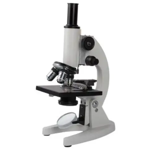
Image 1: The image is a typical compound microscope commonly found in the workplace.
Picture Source: imimg.com
Who invented the compound microscope?
The invention of the compound microscope is credited by historians to Zacharias Janssen, a Dutch spectacle maker, around 1590.
Principles of compound microscope
When a minute object is placed beyond the focus of the objective lens, a highly magnified object is formed at a distance of distinct vision from the eye close to the eye piece. A compound microscope has two convex lenses; an objective lens and eye piece.
The objective lens is placed towards the object and the eyepiece is the lens towards our eye. Both eyepiece and objective lenses have a short focal length and fitted at the free ends of two sliding tubes. (4, 5, and 6)
Compound microscope parts and magnification
A compound microscope consists of different parts and each part plays an important function. These include the following:
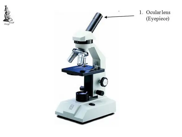
Image 2: The eyepiece/ocular lens of a compound microscope.
Picture Source: slideplayer.com
- Eyepiece/ocular lens – It is the part of the microscope that is looked through at the top. It comes with a magnification ranging between 5x and 30x.
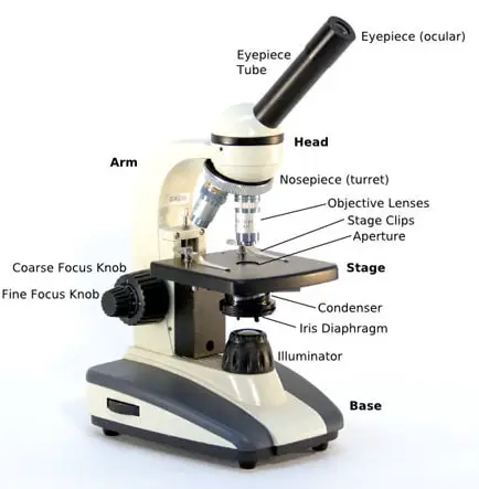
Image 3: The head connects the eyepiece to the objective lens.
Picture Source: microscope.com
- Head (monocular/binocular) – It is the structural support of the microscope. It holds and connects the eyepiece to the objective lens.
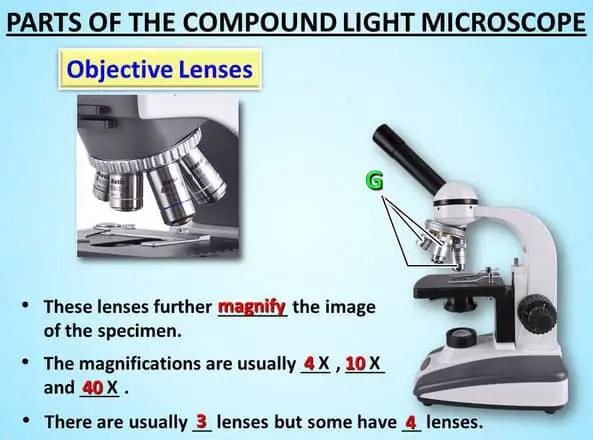
Image 4: The objectives of a compound microscope.
- Objective lens – A compound microscope has three to five optical lens objectives and each comes with various magnification level (4x, 10x, 40x, and 100x). To calculate the total magnification of the microscope, all you need to do is to multiply the objective lens magnification by eyepiece magnification level.
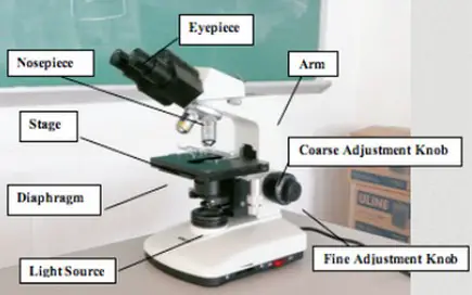
Image 5: The arm of the compound microscope.
Picture Source: zfic.org
- Arm – it supports the head of the microscope and attach it to the base.
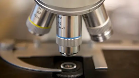
Image 6: The revolving nosepiece.
Picture Source: img-aws.ehowcdn.com
- Nosepiece – It holds the objective lens and attaches them to the head of the microscope. You can rotate the nosepiece to change the objective lens.
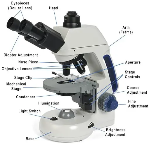
Image 7: The base is the bottom part of the microscope .
Picture Source: microscopeinternational.com
- Base – It supports the microscope and houses the illumination of the microscope.
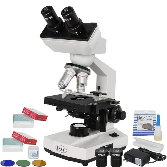
Image 8: A sliding glass is needed and is attached to the stage using a stage clip.
Picture Source: images-na.ssl-images-amazon.com
- Sliding glass – It holds the specimen for easy viewing. It is made of thin rectangular glass.
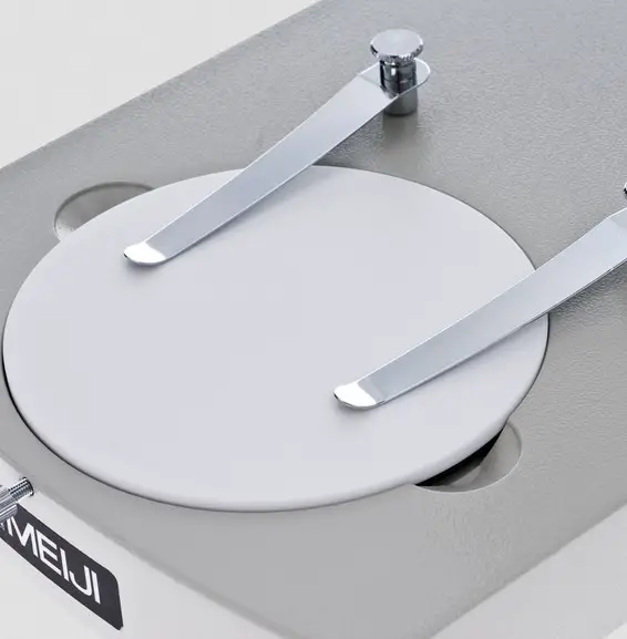
Image 9: This is how a stage clip looks like.
Picture Source: microscope.com
- Stage clip – It clips/holds the sliding glass in place.
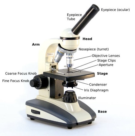
Image 10: The stage is where the sliding glass with a specimen is placed,
- Stage/platform – It is where the specimen or slide is placed.
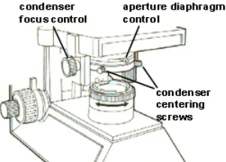
Image 11: The aperture diaphragm control.
Picture Source: stevegallik.org
- Aperture – It is disc characterized by its circular opening where the illumination from the base reaches the platform stage.
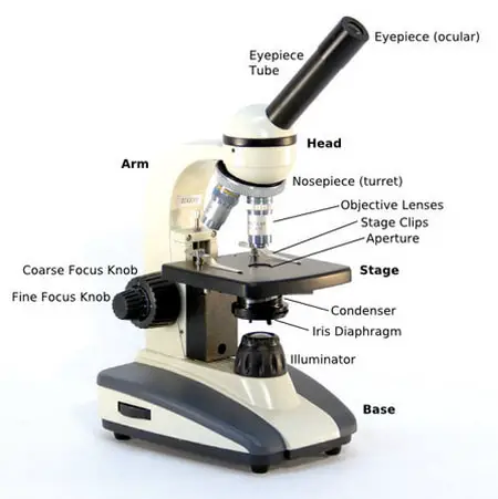
Image 12: The condenser is underneath the stage.
- Abbe condenser – It is a lens that condenses the light from the base illumination and directed it to the stage.
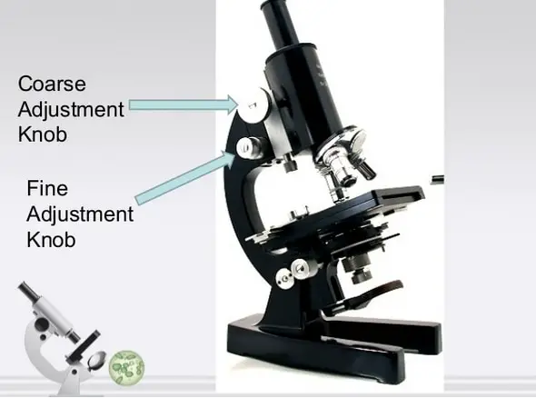
Image 13: The coarse and fine adjustment knobs.
Picture Source: boruhealthmachine.org
- Coarse focus – Use this knob with the lowest power objective to get the subject in focus.
- Fine focus – It is the smaller of the two focus knobs. It is the commonly used focus in viewing the slides.
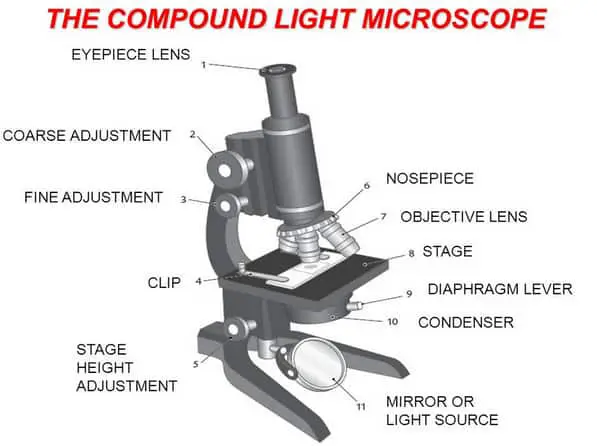
Image 14: The stage height adjustment is at the bottom left.
- Stage height adjustment – It allows you to easily adjust the placement of mechanical stage in both horizontal and vertical path. Adjusting the knob is important as it prevents the possibility of contact between the objective lens and slide containing the specimen.
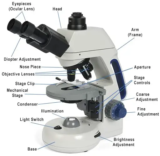
Image 15: The illumination is at the center of the base.
- Illumination – It is the light used to illuminate the slide that contains the specimen. The light comes from the base of the microscope.
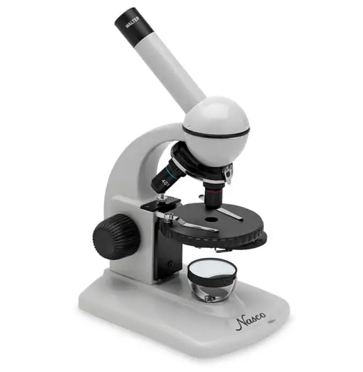
Image 16: Mirror sets on top of the base.
Picture Source: enasco.com
- Mirror – it reflects light into the microscope’s base.
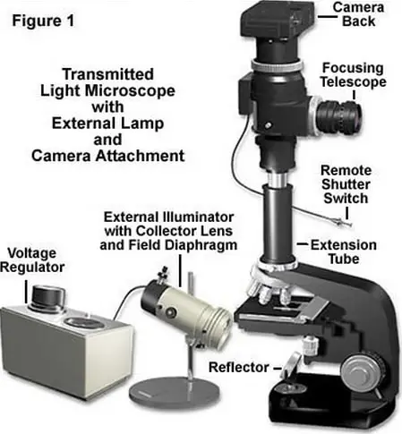
Image 17: The field diaphragm.
Picture Source: olympus-lifescience.com
- Bottom lens/field diaphragm – it is a knob used to adjust the amount of light that gets in contact with the specimen. (5, 6, 7, and 8)
How a compound microscope works/functions?
Light begins at the base of the microscope coming from the source of illumination. It travels upward through the condenser and aperture and passes through the stage. As the light passes through, the image of the specimen on the slide is picked up by the magnification of the objective lens above it. The magnification varies. After which, the light moves to the head of the microscope reaching the eyepiece and magnified by the ocular lenses.
Basically, all the parts of the microscope work together to magnify the specimen and have a clearer view. As someone who is using the microscope, it is important to learn how to properly use and adjust the microscope.
Aside from the proper use of a microscope, it is also important to keep the microscope in perfect shape and one way of doing so is by keeping it clean. (2, 5, 8, and 9)
Why is compound microscope image inverted?
A compound microscope captures an inverted image of the specimen because every time the light passes through the lens, the image’s direction is flipped. The image always ends up inverted from the original. So, if you move the sample to the left, it moves in the right direction.
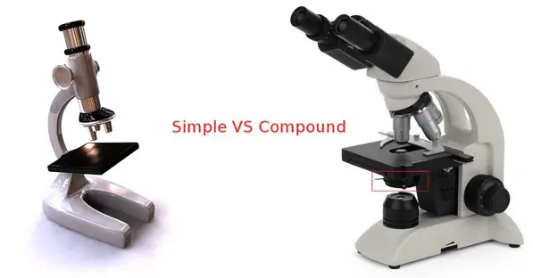
Image 18: A comparison image between a simple and compound microscope.
Picture Source: microscopeheroes.com
What is the difference between a compound microscope and a simple microscope?
- Simple microscope – It is a convex lens of small focal length and its primary use is to see a magnified image of small objects.
- Compound microscope – It is an optical instrument consists of two convex lenses of short focal lengths primarily used for observing a highly magnified image of minute objects.
- Simple microscope – It has a convex lens. It uses only one lens to magnify objects. An example of a simple microscope is a magnifying glass.
- Compound microscope – It has two convex lenses. It is called a compound microscope because it compounds the light as it passes through the lenses to magnify. The image of the object being viewed is enlarged because of the lens near the object. An eyepiece, an additional lens, is where real magnification takes place. The lens of the eye piece magnified the already enlarged image making it larger and clearer. (2, 4, and 6)
Focal Length
The focal length is the distance between the lens and its focus.
- Simple microscope – A simple microscope has a short focal length.
- Compound microscope – They eyepiece makes the focal length longer and more precise. The objective lens and the eyepiece make the object larger and more defined.
Magnification
- Simple microscope – It has a maximum magnifying power of 10. As with the nature of magnification, a simple microscope has a fixed magnification. It magnifies the image to a certain degree that the lens allows.
- Compound microscope – It has the maximum magnifying power of 1000. A compound microscope’s magnification can be multiplied because it has an additional lens. You can magnify to the lens the highest capacity making the image clearer and more defined. (7, 9, and 10)
Presence of condenser lens
- Simple microscope – Absent
- Compound microscope – Present
Source of light
- Simple microscope – Natural
- Compound microscope – Illuminator
Type of mirror
- Simple microscope – Concave reflecting
- Compound microscope – It has both plain and concave type mirror.
Magnification adjustment
- Simple microscope – No
- Compound microscope – Yes
Usage/application
- Simple microscope – For simple/basic use.
- Compound microscope – A compound microscope is commonly used for professional research purpose.
Check the table below for a detailed comparison between a simple microscope and a compound microscope.
Compound microscope types
Compound microscopes are categorized into four types. They are the following:
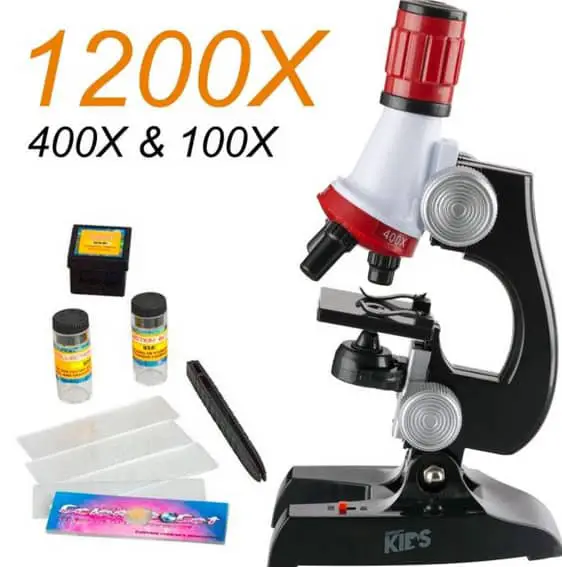
Image 19: A toy compound microscope.
Picture Source: ebayimg.com
- Plastic pipettes
- Prepared specimens
- Ridiculously high magnification
A toy microscope does not have objectives manufactured as per the 160 mm standard. It has a low resolution and it is extremely difficult to achieve focus because its parts are made of plastics.
Another distinct characteristic of the toy compound microscope is its low field of view and low brightness.
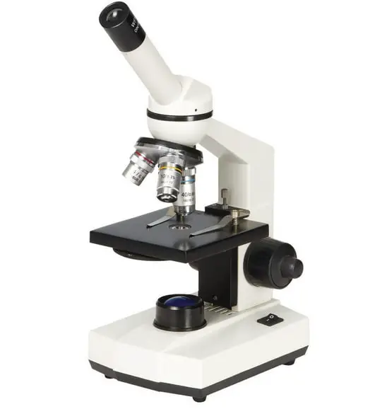
Image 20: A compound microscope typically used in schools.
Picture Source: medpro-microscope.com
Educational/student microscope
- This type of compound microscope is small, which makes it a portable device. So, students can bring it with them anytime and anywhere. Its eyepiece has 10x magnification and comes with three objectives: 4x, 10x, and 40x.
- Its light source comes from halogen or LED. Some even have a battery, which enables you to use the microscope even with no power supply. This is the best microscope for an amateur user.
- It is easy to use and adheres with the DIN standardized objectives. Its body is usually made from metal. Some educational/student compound microscopes have a condenser with a diaphragm for you to easily control the resolution, contrast, and depth of field.
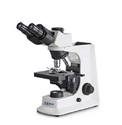
Image 21: A compound microscope typically used in the laboratory setting.
Picture Source: ssl-images-amazon.com
Routine/laboratory microscope
- It is bigger in size when compared with the student microscope. It is also heavier. It is primarily used for laboratory setting. It comes with a wide body and base.
- Its distinct parts include a condenser, illumination, focus lock, mechanical stage, and a revolving nosepiece which can hold up to five objectives. It usually has a binocular head, which makes long-term observation easy.
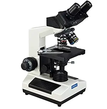
Image 22: An example of a research compound microscope.
Research microscope
- This type of compound microscope is used for extensive research. It is large, heavy, quite modular, not portable, and too expensive when compared with other types of compound microscope.
- It comes with different objectives and filters. (2, 4, 7, 9, 10, and 11)
- https://www.microscopeinternational.com/what-is-a-compound-microscope/
- https://www.microscope.com/compound-microscope-parts/
- https://www2.mrc-lmb.cam.ac.uk/microscopes4schools/microscopes1.php
- http://microscopy.berkeley.edu/courses/tlm/cmpd/cmpd.html
- http://www.funscience.in/study-zone/Physics/OpticalInstruments/CompoundMicroscope.php#sthash.lZVVb7bU.dpbs
- http://www.math.ubc.ca/~cass/courses/m309-03a/m309-projects/yeh/micro.htm
- https://www.martinmicroscope.com/microscopes/
- https://optimaxonline.com/newsdetails.php?newsId=21
- https://courses.lumenlearning.com/ap1x94x1/chapter/the-parts-of-a-compound-microscope-and-how-to-handle-them-correctly/
- http://hyperphysics.phy-astr.gsu.edu/hbase/geoopt/micros.html
- https://staff.concord.org/~btinker/GL/web/water/using_compound_microscope.html
Leave a Reply Cancel reply
Your email address will not be published. Required fields are marked *
Save my name, email, and website in this browser for the next time I comment.
Compound Microscope
As the name suggests, a compound microscope uses a combination of lenses coupled with an artificial light source to magnify an object at various zoom levels to study the object.
A compound microscope:
- Is used to view samples that are not visible to the naked eye
- Uses two types of lenses – Objective and ocular lenses
- Has a higher level of magnification – Typically up to 2000x
- Is used in hospitals and forensic labs by scientists, biologists and researchers to study microorganisms
Invented in the late 16th century by Zacharias Janssen, compound microscopes have contributed immensely to the medical field.
It has helped scientists, researchers and doctors in studying the microorganisms, their cells and DNA.
This understanding of the microorganisms has helped scientists in studying how different conditions and diseases attack various cells in our body and several medical advances have been possible, thanks to the compound microscope.
What actually is a Compound microscope?
- Also called as binocular microscope or compound light microscope, it is a remarkable magnification tool that employs a combination of lenses to magnify the image of a sample that is not visible to the naked eye.
- Compound microscopes find most use in cases where the magnification required is of the higher order (40 – 1000x).
- The magnification effect is achieved using the combination of the objective lens (near the sample) and the ocular lens (within the eyepiece).
- The final magnification achieved by the microscope is measured by multiplying both the magnification achieved by objective lens and the magnification achieved by ocular/eyepiece lens.
Working principle
Using a combination of lenses, the working principle of a compound microscope is that a highly magnified image of the specimen is formed at the least possible distance from the distinct vision of an eye that is held very close to the eyepiece of the microscope when the specimen is placed just beyond the focus of the objective lens.
The magnified image is always an inverted and virtual image of the specimen.
Compound Microscope Parts (Labeled diagram)
A compound microscope basically consists of optical and structural components. Within these two systems, there are multiple components within them and they are:
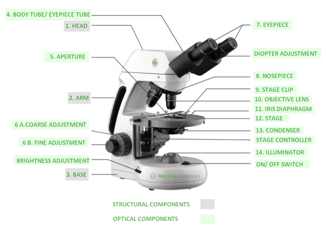
Image : Labeled Diagram of compound microscope parts
See: Labeled Diagram showing differences between compound and simple microscope parts
Structural Components
The three structural components include
This is the upper part of the microscope that houses the optical parts
2. Arm
This part connects the head with the base and provides stability to the microscope. Arm is used to carry the microscope around
3. Base
Base is on which the microscope rests and the base houses the illuminator that lights up the specimens.
Optical Components
Objective lenses and Eyepiece lenses are the two major optical systems in a compound microscope. The various optical components include:
4. Eyepiece Tube
The tube aids in keeping the eyepieces in their place above the objective lens. These binocular microscopes typically have a diopter adjustment ring that is used to adjust for the variations in our eyesight in one or both eyes.
5. Aperture
The stage has a hole through which the transmitted light from the base falls on the stage to illuminate the slide. This hole is called the aperture.
6 (a,b). Fine and Coarse Focus knobs
These knobs are used to adjust the focus of the microscope. In the recent past, these two knobs are coaxial housed to offer convenience to the user. Usually, both the knobs are built on one axis with the fine focus knob placed on the outside to enable the users to fine tune the focus.
7. Eyepiece
The eyepiece is at the top of the microscope and it is through this we see the specimen. Eyepieces usually have a magnifying power of 10x and the magnifying power can be increased or decrease depending on the usage by interchanging the lenses.
8. Nosepiece
This is the part that hosts the objective lenses. The objective lenses are mounted on a rotating turret and different lenses can be selected and exposed depending on the user’s requirement.
9. Stage Clips
These clips are used when there is no mechanical stage. The user needs to manually move the slide containing the specimen to view the various sections within the sample.
10. Objective Lens
The most important optical component on the microscope, objective lens can have a magnifying power ranging from 4x to 100x. A combination of about 4 – 5 lenses are used on microscopes depending on the required magnifying power.
Depending on the level of complexity of the specimen, the magnifying power is chosen and accordingly the lenses are used. These objective lenses can be either rear-facing or forward-facing.
11. Iris Diaphragm
It regulates the amount of light reaching the specimen that needs to be viewed under the microscope. It is located under the stage and over the condenser. Modern day microscopes use a combination of condenser and iris diaphragm to control the quantity of light and focus being applied to the specimen.
The specimen that is to be viewed is placed on the stage. Depending on the requirement of working at higher magnifications, a mechanical stage is used to enable the delicate movements that may be required with the specimen.
13. Condenser
It collects and focuses the light from the illuminator onto the specimen. It is housed under the stage and is often used in combination with the iris diaphragm.
14. Illuminator
This is the light source for the microscope and is usually located in the base of the microscope. The modern day microscopes use halogen bulbs operating at low voltage and have the capability to operate at variable lighting settings to facilitate convenience for users.
For instance, the users can increase or decrease the intensity of light being focused on the specimen being viewed. The lighting control is incorporated in the base of the microscope.
15. Condenser Focus Knob
This knob is used to control the movement of the condenser in the process of controlling the light focus on the specimen
16. The Rack stop
This component regulates the movement of the stage lest the specimen gets in contact with the lens thereby increasing the chances of damaging the specimen.
For in-detail information on: Parts of Compound microscope
Frequently asked Questions
Q 1. what is a compound microscope and how does it work.
A compound microscope uses a combination of lenses coupled with an artificial light source to magnify an object at various zoom levels to study the object.
Q 2. What is the principle of compound microscope?
Q 3. why is it called compound microscope.
Because it has multiple lenses that work in conjunction to magnify a specimen
Q 4. What are the 13 parts of a microscope?
1. Eyepiece 2. Eyepiece Tube 3. Objective Lens 4. Stage 5. Stage Clips 6. Nosepiece 7. Fine and Coarse Focus knobs 8. Illuminator 9. Aperture 10. Iris Diaphragm 11. Condenser 12. Condenser Focus Knob 13. The Rack stop
Q 5. What are the 11 parts of a compound microscope?
The most important parts of a compound microscope are:
– Eyepiece & Eyepiece Tube – Objective Lens – Stage – Stage Clips – Nosepiece – Fine and Coarse Focus knobs – Illuminator – Aperture – Iris Diaphragm
Q 6. What are the advantages of a compound microscope?
– Ease of use – Affordable compared to electron microscope – Can be used to view live samples – Has an in-built light source that illuminates the specimen – Relatively small in size and can magnify up to 2000x
Q 7. What are the disadvantages of compound microscope?
– Higher order of magnification is not possible (over 2000x) – Atoms, molecules and viruses can’t be viewed using compound microscope
Q 8. Can we examine viruses using a compound microscope?
Q 9. what are the types of compound microscope.
Different types of compound microscopes include:
1. Biological microscopes 2. Phase contrast microscopes 3. Polarizing microscopes 4. Fluorescence microscopes
Q 10. Which lens is used in compound microscope?
A compound microscope uses two convex lenses. The objective lens – used near the specimen – and the ocular lens that is closer to the eye.
Q 11. Who discovered the compound microscope?
Zacharias Janssen invented the compound microscope in late 16th century
Q 12. What are main parts of microscope?
The three structural components include:
1. Head – This is the upper part of the microscope that houses the optical parts 2. Arm – This part connects the head with the base and provides stability to the microscope. Arm is used to carry the microscope around 3. Base – Base is on which the microscope rests and the base houses the illuminator that lights up the specimens
Q 13. What are the optical parts of microscope?
Objective lenses and Eyepiece lenses are the two major optical systems in a compound microscope.
Q 14. What are the illuminating parts of a compound microscope?
Condenser – It collects and focuses the light from the illuminator onto the specimen. It is housed under the stage and is often used in combination with the iris diaphragm
Q 15. What does a diaphragm do in a microscope?
Diaphragm – It regulates the amount of light reaching the specimen that needs to be viewed under the microscope. It is located under the stage and over the condenser. Modern day microscopes use a combination of condenser and iris diaphragm to control the quantity of light and focus being applied to the specimen
Q 16. What is the use of eyepiece in compound microscope?
The eyepiece is at the top of the microscope and it is through this we see the specimen. Eyepieces usually have a magnifying power of 10x and the magnifying power can be increased or decrease depending on the usage by interchanging the lenses
References:
Leave a Reply Cancel reply
Your email address will not be published. Required fields are marked *
Save my name, email, and website in this browser for the next time I comment.

- school Campus Bookshelves
- menu_book Bookshelves
- perm_media Learning Objects
- login Login
- how_to_reg Request Instructor Account
- hub Instructor Commons
Margin Size
- Download Page (PDF)
- Download Full Book (PDF)
- Periodic Table
- Physics Constants
- Scientific Calculator
- Reference & Cite
- Tools expand_more
- Readability
selected template will load here
This action is not available.

3.8: The Compound Microscope
- Last updated
- Save as PDF
- Page ID 57092
\( \newcommand{\vecs}[1]{\overset { \scriptstyle \rightharpoonup} {\mathbf{#1}} } \)
\( \newcommand{\vecd}[1]{\overset{-\!-\!\rightharpoonup}{\vphantom{a}\smash {#1}}} \)
\( \newcommand{\id}{\mathrm{id}}\) \( \newcommand{\Span}{\mathrm{span}}\)
( \newcommand{\kernel}{\mathrm{null}\,}\) \( \newcommand{\range}{\mathrm{range}\,}\)
\( \newcommand{\RealPart}{\mathrm{Re}}\) \( \newcommand{\ImaginaryPart}{\mathrm{Im}}\)
\( \newcommand{\Argument}{\mathrm{Arg}}\) \( \newcommand{\norm}[1]{\| #1 \|}\)
\( \newcommand{\inner}[2]{\langle #1, #2 \rangle}\)
\( \newcommand{\Span}{\mathrm{span}}\)
\( \newcommand{\id}{\mathrm{id}}\)
\( \newcommand{\kernel}{\mathrm{null}\,}\)
\( \newcommand{\range}{\mathrm{range}\,}\)
\( \newcommand{\RealPart}{\mathrm{Re}}\)
\( \newcommand{\ImaginaryPart}{\mathrm{Im}}\)
\( \newcommand{\Argument}{\mathrm{Arg}}\)
\( \newcommand{\norm}[1]{\| #1 \|}\)
\( \newcommand{\Span}{\mathrm{span}}\) \( \newcommand{\AA}{\unicode[.8,0]{x212B}}\)
\( \newcommand{\vectorA}[1]{\vec{#1}} % arrow\)
\( \newcommand{\vectorAt}[1]{\vec{\text{#1}}} % arrow\)
\( \newcommand{\vectorB}[1]{\overset { \scriptstyle \rightharpoonup} {\mathbf{#1}} } \)
\( \newcommand{\vectorC}[1]{\textbf{#1}} \)
\( \newcommand{\vectorD}[1]{\overrightarrow{#1}} \)
\( \newcommand{\vectorDt}[1]{\overrightarrow{\text{#1}}} \)
\( \newcommand{\vectE}[1]{\overset{-\!-\!\rightharpoonup}{\vphantom{a}\smash{\mathbf {#1}}}} \)
A magnifier alone can provide very high magnification only at the cost of intolerable aberrations. The compound microscope is a magnifier of close objects with a high angular magnification, generally more than \(30 \times\) . It was invented by Zacharias Janssen in Middelburg in 1590 (this claim is disputed). The first element of the compound microscope is an objective (in Figure \(\PageIndex{1}\) a simple positive lens) which makes a real, inverted and magnified image of the object in the front focal plane of an eyepiece (where there is also the field stop). The eyepiece will make a virtual image at infinity, as explained above. The magnifying power of the entire system is the product of the transverse linear magnification of the objective \(M_{T}\) and the angular magnification of the eyepiece \(M_{A e}\) : \[\mathrm{MP}=M_{T} M_{A e} . \nonumber \]
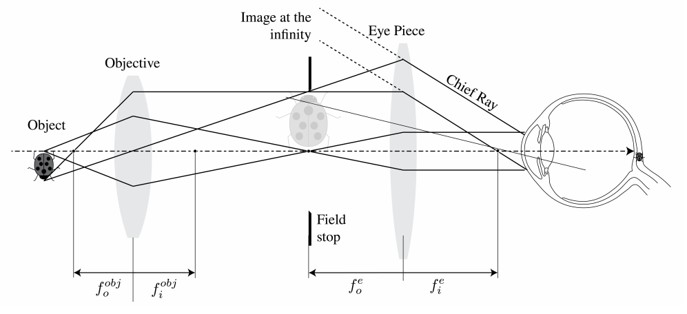
According to (2.5.51): \(M_{T}=-x_{i} / f_{i}^{o b j}\) , where \(x_{i}\) is the distance of the image made by the objective to its back focal plane with focal distance \(f_{i}^{\text {obj }}\) . We have \(x_{i}=L\) which is the tube length, i.e. the distance between the second focal point of the objective and the first focal point of the eyepiece. The tube length is standardised at \(16 \mathrm{~cm}\) . Furthermore, according to (3.5.5), the angular magnification is for a virtual image at infinity \(M_{A e}=d_{o} / f_{i}^{e}\) . Hence, we obtain: \[\mathrm{MP}=\frac{-x_{i}}{f_{i}^{o b j}} \frac{d_{o}}{f_{i}^{e}}=\frac{-16}{f_{0}} \frac{25}{f_{e}}, \nonumber \] with the standard near-point \(d_{o}=25 \mathrm{~cm}\) . As an example, an Amici objective gives \(40 \times\) and combined with a \(10 \times\) eye piece one gets \(M P=400\) .
The Numerical aperture of a microscope is a measure of the capability to gather light from the object. It is defined by: \[\mathrm{NA}=n_{i m} \sin \theta_{\max } \nonumber \] with \(n_{\text {im }}\) the refractive index of the immersing medium, usually air, but it could be water or oil, and \(\theta_{\max }\) , the half-angle of the maximum cone of light accepted by the lens. The numerical aperture is the second number etched in the barrel of the objective. It ranges from \(0.07\) (lowpower objectives) to \(1.4\) for high-power objectives. Note that it depends on the object distance. In Chapter 7 it will be explained that NA is for the a given object distance proportional to the resolving power, which is the minimum transverse distance between two object points that can be resolved in the image.
- What's New Here!
- The World of Microorganisms
- Cell Biology
- Plant Biology
- Understanding Phylum
- All about Fungi
- All about Bacteria
- Fascinating Tardigrades
- White Blood Cells
- Imaging Techniques
- Microscope Applications
- The Wonders of Nanotechnology
- Microscope History-Invention
- Microscope Quiz
- Privacy Policy
- Microbiology
- Bacteriology
- Parasitology
- Microscope Slides
- Microscope Function
- Cleaning Your Scope
- Experiments
- Cell Staining
- Different Types
- USB Computer
- Digital Camera
- Microscope Kits
- Student/Homeschool
- Younger Kids/Homeschool
- Metallurgical
- Scanning Probe
- AmScope Guide
- Levenhuk **NEW
Microscope Parts and Functions With Labeled Diagram and Functions How does a Compound Microscope Work?
Before exploring microscope parts and functions , you should probably understand that the compound light microscope is more complicated than just a microscope with more than one lens.
Please enable JavaScript

Here are the important compound microscope parts...
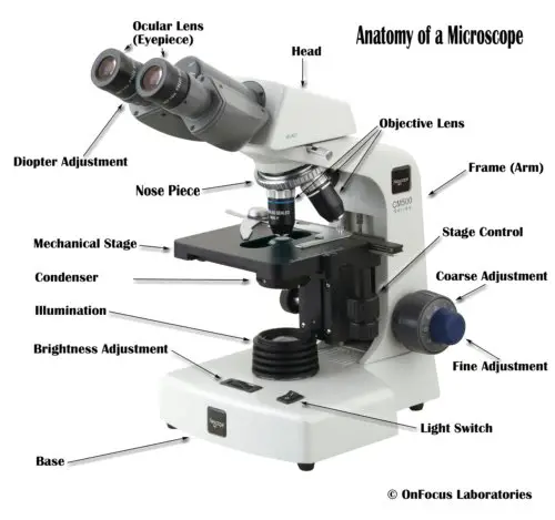
Eyepiece: The lens the viewer looks through to see the specimen. The eyepiece usually contains a 10X or 15X power lens.
Diopter Adjustment: Useful as a means to change focus on one eyepiece so as to correct for any difference in vision between your two eyes.
Body tube (Head): The body tube connects the eyepiece to the objective lenses.
Arm: The arm connects the body tube to the base of the microscope.
Coarse adjustment: Brings the specimen into general focus.
Fine adjustment: Fine tunes the focus and increases the detail of the specimen.
Nosepiece: A rotating turret that houses the objective lenses. The viewer spins the nosepiece to select different objective lenses.
Objective lenses : One of the most important parts of a compound microscope, as they are the lenses closest to the specimen.
A standard microscope has three, four, or five objective lenses that range in power from 4X to 100X. When focusing the microscope, be careful that the objective lens doesn’t touch the slide, as it could break the slide and destroy the specimen.
Specimen or slide : The specimen is the object being examined. Most specimens are mounted on slides, flat rectangles of thin glass.
The specimen is placed on the glass and a cover slip is placed over the specimen. This allows the slide to be easily inserted or removed from the microscope. It also allows the specimen to be labeled, transported, and stored without damage.
Stage: The flat platform where the slide is placed.
Stage clips: Metal clips that hold the slide in place.
Stage height adjustment (Stage Control): These knobs move the stage left and right or up and down.
Aperture: The hole in the middle of the stage that allows light from the illuminator to reach the specimen.
On/off switch: This switch on the base of the microscope turns the illuminator off and on.
Illumination: The light source for a microscope. Older microscopes used mirrors to reflect light from an external source up through the bottom of the stage; however, most microscopes now use a low-voltage bulb.
Iris diaphragm: Adjusts the amount of light that reaches the specimen.
Condenser: Gathers and focuses light from the illuminator onto the specimen being viewed.
Base: The base supports the microscope and it’s where illuminator is located.
How Does a Compound Microscope Work?
All of the parts of a microscope work together - The light from the illuminator passes through the aperture, through the slide, and through the objective lens, where the image of the specimen is magnified.
The then magnified image continues up through the body tube of the microscope to the eyepiece, which further magnifies the image the viewer then sees.
Learning to use and adjust your compound microscope is the next important step.
It's also imperative to know and understand the best practices of cleaning your microscope .
The microscope parts work together in hospitals and in forensic labs, for scientists and students, bacteriologists and biologists so that they may view bacteria, plant and animal cells and tissues, and various microorganisms the world over.
Compound microscopes have furthered medical research, helped to solve crimes, and they have repeatedly proven invaluable in unlocking the secrets of the microscopic world.
Check out MicroscopeMaster’s online help:
Basics of a Compound Microscope
Diagram/Parts/Functions of a Compound Microscope
Beginner Microscope Experiments
Microscope Slides Preparations-Styles and Techniques
Prepared Microscope Slides - Benefits and Recommendations
See also: Dissecting Stereo Microscope Parts and Functions
Stereo Microscope Vs Compound Microscope
Check out this Microscope Quiz to test your knowledge
Interesting info here on Basic Microscope Ergonomics
Return from Parts of a Compound Microscope to Compound Light Microscope
Return from Parts of a Compound Microscope to Best Microscope Home
Find out how to advertise on MicroscopeMaster!

MicroscopeMaster.com is a participant in the Amazon Services LLC Associates Program, an affiliate advertising program designed to provide a means to earn fees by linking to Amazon.com and affiliated sites.
Recent Articles
Deltaproteobacteria - Examples and Characteristics
Nov 01, 22 04:44 PM
Chemoorganotrophs - Definition, and Examples
Oct 26, 22 05:01 PM
Betaproteobacteria – Examples, Characteristics and Function
Oct 25, 22 03:44 PM
The material on this page is not medical advice and is not to be used for diagnosis or treatment. Although care has been taken when preparing this page, its accuracy cannot be guaranteed. Scientific understanding changes over time.
** Be sure to take the utmost precaution and care when performing a microscope experiment. MicroscopeMaster is not liable for your results or any personal issues resulting from performing the experiment. The MicroscopeMaster website is for educational purposes only.
Privacy Policy by Hayley Anderson at MicroscopeMaster.com All rights reserved 2010-2021
Amazon and the Amazon logo are trademarks of Amazon.com, Inc. or its affiliates
Images are used with permission as required.
If you're seeing this message, it means we're having trouble loading external resources on our website.
If you're behind a web filter, please make sure that the domains *.kastatic.org and *.kasandbox.org are unblocked.
To log in and use all the features of Khan Academy, please enable JavaScript in your browser.
Optics (Essentials) - Class 12th
Course: optics (essentials) - class 12th > unit 3.
- Human eye: accommodation and near point
- Power of accommodation
- Simple microscope
- Simple microscope - max & min power
- Simple Microscope - qualitative
- Compound microscope
Compound Microscope
- Solved example: magnifying power of compound microscope
- Your answer should be
- an integer, like 6
- a simplified proper fraction, like 3 / 5
- a simplified improper fraction, like 7 / 4
- a mixed number, like 1 3 / 4
- an exact decimal, like 0.75
- a multiple of pi, like 12 pi or 2 / 3 pi

1 Visualizing Cells through Microscopy
Visualizing cells through microscopy, introduction.
Before we can even begin to discuss cells, it’s important to understand that cells are very tiny! Most cells are too small to see with the naked eye. Thus, the beginning of our book must start with a conversation about microscopes and how they work. An understanding of the tools we use to study cells, both their abilities and their limitations, is essential to making sense of the material you’re going to be exploring throughout this book. These days, thanks to some pretty impressive advances in computing in the last 50 years or so, there are a great many different types of microscopes that exist. We can’t possibly cover all of the different kinds with the time that we have to cover this topic. However, the essence of all of the varied types of microscopes that are used to explore cell biology fit into four major groupings:
- Brightfield light microscopy
- Fluorescene light microscopy
- Transmission electron microscopy (TEM)
- Scanning electron microscopy (SEM)
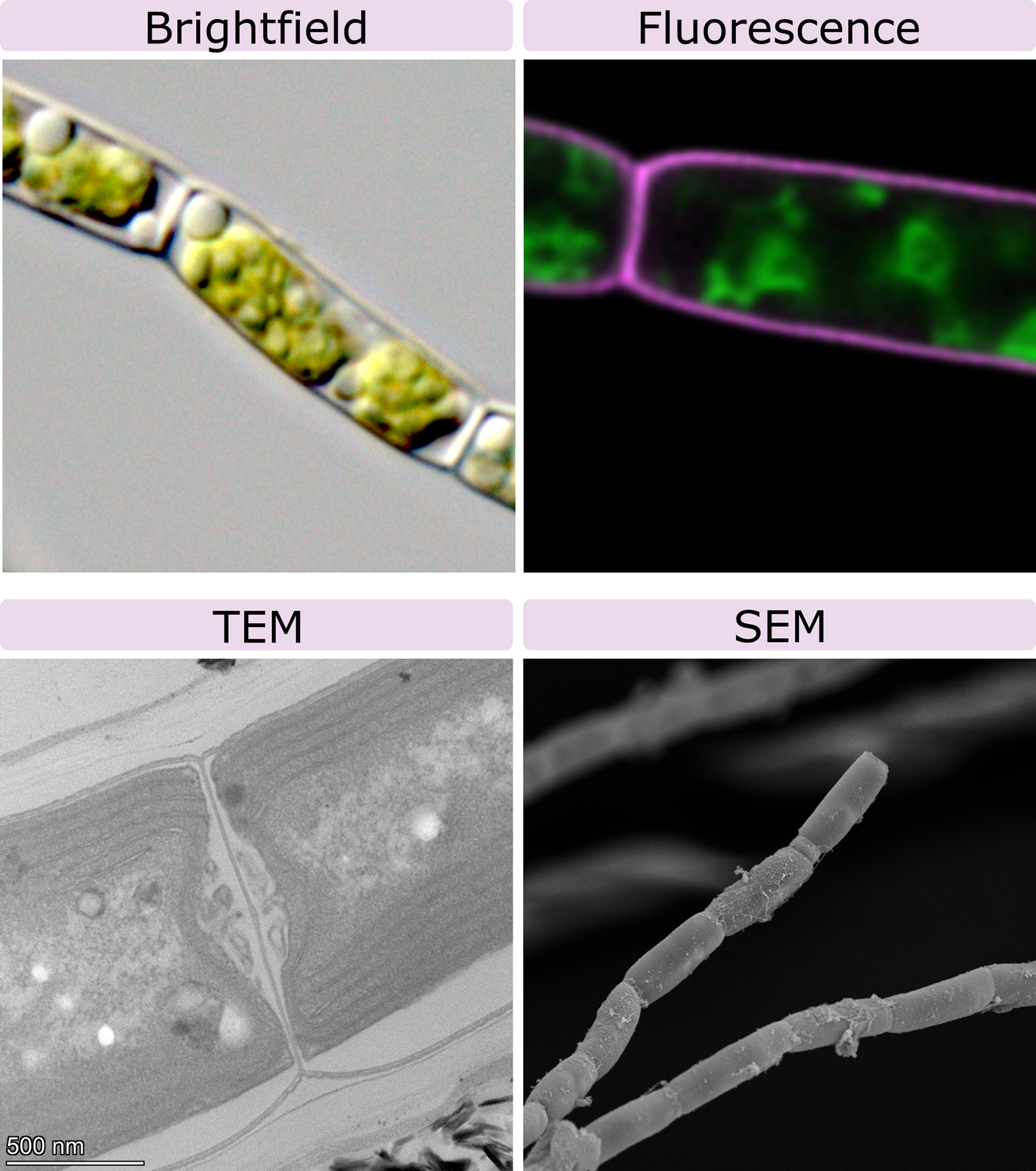
The capacity to visualize samples in any kind of microscope depends on the particle that is used by that microscope. The first and oldest microscopes were developed about 400 years ago and used visible light from the sun, with glass lenses to magnify the sample. About 80–100 years ago, we discovered that using electrons to image samples greatly increased both the magnification and resolution of the microscope. These days, both light and electron microscopy are still in use. We will look at each type of microscopy in turn and explore their strengths and limitations. An example of each is included in Figure 01-01 for direct comparison in the same organism. We will also show more examples throughout the chapter. Consider how we might identify each type of microscopy and distinguish when we could use one type over the other. However, before we do any of that, we must first discuss the concepts of magnification and resolution , since all microscopes use both to help us see very small objects, like cells.

Topic 1.1: Magnification and Resolution
Learning goals.
- Define magnification and resolution.
- Explain how magnification and resolution work together to help us see cellular structures more clearly.
Before we take a deeper dive into the topic of microscopy, it may be useful to revisit the physics behind how microscopes work. It’s important to understand the basic principles of the wave/particle properties of visible light , which is one small section of the electromagnetic spectrum . Electrons also have both wave and particle-like properties, so many of the principles that underlie electron microscopy are similar to those that underlie light microscopy. Fluorescence microscopy and scanning electron microscopy (SEM) are derivatives of the other two, in which the source of the particle and/or the way the particle is detected is changed so that a different image is created.
All microscopes have limitations on the size and detail with which they can be used to visualize objects. These limitations are a product of the specific characteristics of the particle being used to create the image (i.e., photons or electrons). The wavelength at which these particles travel has a direct impact on how much detail can be seen in the image generated. When discussing the limitations of microscopes, we generally discuss them in terms of magnification and resolution.
The Merriam-Webster Dictionary defines magnification as “the apparent enlargement of an object by an optical instrument.” In other words, a microscope allows us to make very tiny things look bigger than they are. The objectives on a standard classroom microscope often tell you their magnifying power so that you have some context for the actual size of the things that you can see using the lens.
On the other hand, resolution is defined as the closest spacing of two lines that can be distinguished as separate entities. The resolution of any microscope is limited by the wavelength of the particle being used to illuminate it. In the case of the light microscope, the resolution (d) is
[latex]\text{d} = 0.61 * \text{wavelength}/\text{numerical aperture of the objective.}[/latex]
If we consider that the shortest wavelength of light that we can see (violet) is about 400 nm, then our calculation for the resolution of a standard light microscope is as follows:
A standard 63× magnification oil-immersion lens (often the highest magnification available in those classroom microscopes) has a numerical aperture of 1.4. So based on this, the resolution of a standard classroom light microscope with that objective would be 0.61*400 nm/1.4, which equals about 175 nm, or roughly 0.2 µm.
This is pretty small. At that range, we can probably see bacteria and maybe even some large viruses (but not all and definitely not well). We also can see some of the larger subcellular organelles in a cell (like the nucleus and mitochondria), but not much of the smaller organelles. Also, any structure that we can see that’s close to the limit of resolution of the light microscope won’t have much detail visible. Much like if you see someone who is very far away, you may only be able to tell that they are a human, but not if it’s someone that you know.
Electrons, on the other hand, have a much shorter wavelength than photons of the visible light spectrum…roughly 200,000 times smaller! Because of that, the resolution limit of an electron microscope is much smaller…there are some kinds of electron microscopes that can view individual atoms! More commonly, in the more widely used electron microscopes, the resolution limit is roughly 0.1 nm. A single double helix of DNA is 2 nm in diameter, and the thickness of the average lipid bilayer is between 4 and 10 nm. We can see both of these in an electron microscope. As such, we can see that this resolution limit is small enough that a lot of the finer structural details inside the cell become visible.
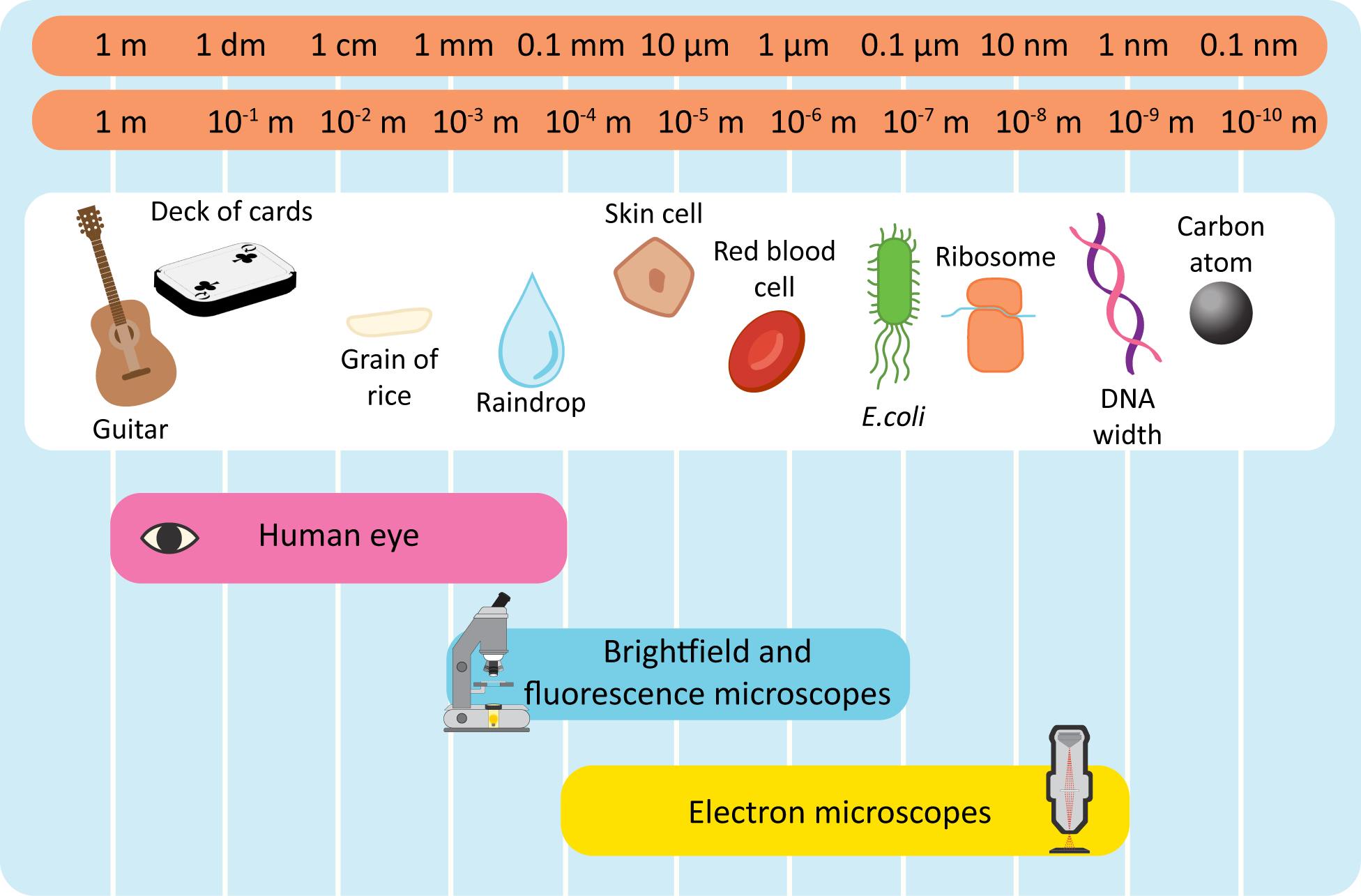
Figure 01-02 gives a rough estimate of what we can see using light or electron microscopy. The website Size of the Universe is also worth exploring. It shows examples that range from the largest thing known (the entire observed universe, or ~10 27 m) down to the smallest theoretical measurable length in the universe (Planck’s length, or 10 -35 m).
It’s important to remember that resolution is a quality that is separate from magnification. The magnification of an image is simply how much we have enlarged the object in order to observe it. For example, if you wanted to blow up a photo to hang on your wall, you would have to increase the magnification in order to do so. If there aren’t enough pixels in your image to support the amount that you’re magnifying it, then at some point the quality of the image will decrease as you increase the magnification. You can’t actually see more detail; you just see the pixels more obviously. The number of pixels the image contains will determine how much detail you can see. Thus, the number of pixels dictates the resolution of the image that you can create, especially as you blow the image up larger and larger. Applying this to microscopy, in order to see small structures, you not only have to have a higher magnification in order to zoom in, but you also need higher resolution in order to see the details of the smaller structures. Figure 01-03 shows a comparison of microscopy at the same magnification with different resolution to highlight why increased resolution is required with an increase in magnification.
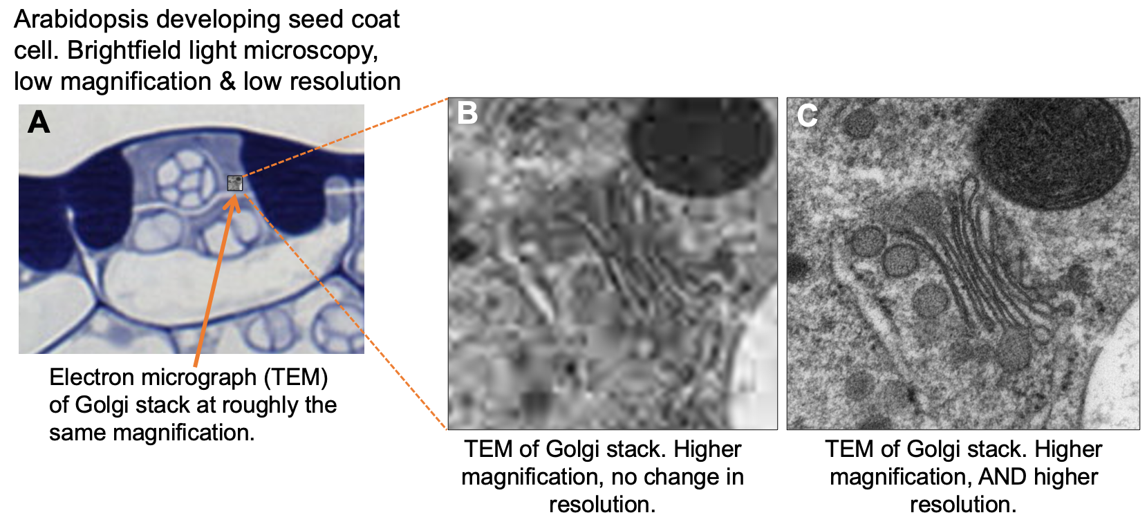
With microscopes, as with the photos that you take with your phone, it is important that the resolution increases along with the magnification in order to see the details desired in the image. The kinds of microscopy that we will explore have different resolution limits. Thus, the resolution that is required in order to observe the structure that you’re interested in will be a major factor when considering the type of microscopy to use in any given situation.
We will leave the final word on this to the following video, created specifically to help you think about the differences between magnification and resolution and also consider how to interpret images when the microscope requires us to cut the sample into thin sections.
Topic 1.2: Light Microscopy
- Explain the basics of how a light microscope works, with a particular focus on how we can use that information to interpret micrographs.
- Compare and contrast the different types of light microscopy (i.e., brightfield versus fluorescence) and identify when each type would be useful.
- Identify the major advantages and disadvantages of light microscopy.
The very first microscope was made in the mid-1600s by a British man named Robert Hooke. That microscope had a mirror to direct sunlight into the glass lenses of the microscope so that the sample could be viewed. Microscopes stayed more or less the same for the next 300 years, until the Industrial Revolution of the early 1900s. It is at this point that the advances in technology allowed us to greatly improve how microscopes work. Now there are light microscopes that use various combinations of lasers, lenses, spinning discs, and computer algorithms to push beyond what should be possible given the physical limitations of visible light. We’ve also made significant advances in sample preparation, which have made additional contributions to what we can visualize. Even though we have incredibly advanced microscopy techniques with which to view cells, their essence remains the same. We will explore the two largest categories of light microscopes: those that collect transmitted light, originating from some kind of light source, to view the sample and those that collect light that is emitted by the sample itself.
Pros to Light Microscopy
Live cells can be viewed and recorded in real time. Specific structures can be labeled for viewing, thus reducing the “noise” in the sample and showing finer details that may otherwise be masked by other components of the sample.
Cons to Light Microscopy
The limit of conventional (brightfield and confocal microscopy) resolution is about 0.2 µm, which restricts the amount of detail we can see of internal cellular structures using light microscopy.
- There is a newer technique, known as superresolution microscopy , which is technically able to break this barrier. We will discuss this in more detail later.
Transmitted versus Emitted Light
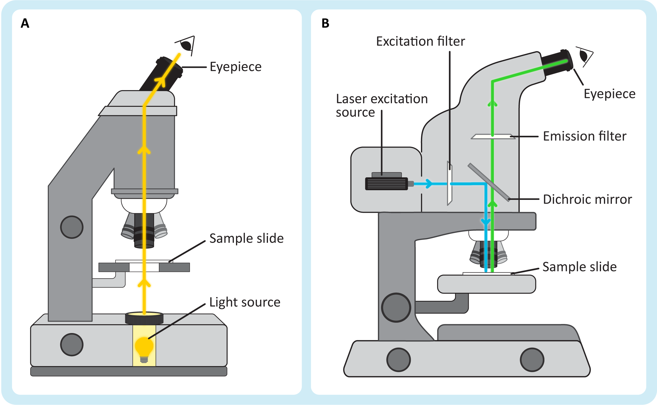
Light microscopy can be further divided into several subtypes of light microscopy. The most notable of these subdivisions takes into account the types of light that you are viewing when you look at an image (Figure 01-04).
- Transmitted light microscopy (Figure 01-04A) is the traditional light microscopy that you most likely tried in high school biology classes. In this type of microscopy, the sample sits between the light source and the eyepiece, and the light you see is the light that was able to pass through the sample. The simplest version, which is the one we will discuss, is called brightfield light microscopy .
- In emitted light microscopy (Figure 01-04B), the sample is illuminated by a light source that is off to the side, and then the molecules in the sample get excited by this light and release their own photons. Thus, the light that you view in these kinds of microscopes comes from the samples themselves. This type of microscopy is also known as fluorescence light microscopy , which is what we will be calling it after this.
Brightfield and Other Forms of Transmitted Light Microscopy
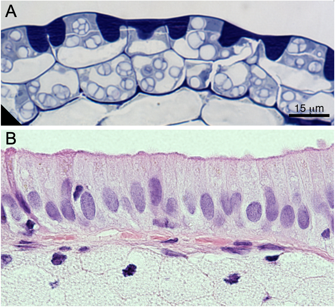
One of the primary challenges of microscopy is that living cells are fairly transparent. Microscopists use a number of techniques to increase the contrast of their samples in order to see things more clearly. Sometimes we add chemical stains to the sample, such as toluidine blue or hematoxylin and eosin (H&E), which add color contrast (see Figure 01-05). We can also use optical techniques, in which certain light is included or excluded from viewing by the microscope, to increase the contrast of our samples. An example of an optical technique used in our daily lives is polarized sunglasses. The polarized glasses reduce glare by only allowing light to pass through if it is oriented in a specific way. We can do similar kinds of things with microscopes. Some of the subtypes of transmitted light microscopy are listed below:
- Brightfield microscopy : If you have ever used a light microscope in school, this is most likely the kind that you used. It was the first invented, way back in the 1600s, and uses a light source as simple as sunlight. Images from this kind of microscopy usually have a white background, and the sample is expected to be in color when we look through the eyepiece of the microscope. Figure 01-05 shows a few different samples that have been stained and observed using brightfield light microscopy. This is the type that we focus on in this textbook when discussing transmitted light microscopy.
- Phase-contrast microscopy : In this type of microscopy, shifts in the amplitude and phase of the light are converted into shifts in brightness so that edges and other structures become more visible. Differential interference contrast (DIC) is a variation on this.
- Darkfield microscopy : In darkfield microscopy, light is excluded by blocking the center of the beam but not the outer part. This kind of light microscopy has a dark background (unlike other kinds of light microscopy), which again helps the edges of cells and other structures in the sample to stand out.
- Polarized light microscopy : This type of microscopy enhances the contrast of specimen by shining light of a particular orientation that causes shadows on structures differentially depending on their composition. This kind of microscopy is especially useful for samples like bone, fibers, or mineral deposits.
Fluorescence Light Microscopy
Fluorescence microscopy was first developed in the 1980s and has continued to revolutionize cell biology to this day. Not only does it allow us to view live samples, as other forms of light microscopy do, but it also allows us to label (or tag) specific macromolecules / cell structure so that we can track them within the cell (Figure 01-04B). We tag the structures using fluorescent molecules (called fluorochromes or fluorophores). Then, using our fluorescent microscope, we illuminate the sample with light of a particular wavelength, and the fluorophore responds by emitting light at a second known wavelength that we can then detect. The great advantage of this technique is that only the molecule or structure of interest shows up in the image, and the rest of the sample, which is not emitting light, is dark.
Much like transmitted light microscopy, there are several subtypes of fluorescent light microscopy. Most of these have been developed to increase the resolution of the images that are being viewed. The simplest type of fluorescence microscopy is known as epifluorescence , which uses powerful halogen lightbulbs and colored filters to produce light of specific wavelengths. Confocal laser scanning microscopy (or confocal for short) is very similar to epifluorescence, except a laser is used as the source of light. Using a laser allows us to focus the light very specifically and then use computer algorithms to remove out-of-focus light. There are also a number of extremely advanced techniques that allow us to seemingly “break” the laws of physics. Using a combination of computer algorithms and specific image collection protocols, microscopists have been able to resolve structures that should be much too small to see in light microscopy. These techniques are collectively known as superresolution microscopy .
Unlike the different kinds of transmitted light microscopy, the images that you create from the different subtypes of fluorescence light microscopy are very similar. It’s not always easy to tell what kind of fluorescence microscope was used to create the image just by looking at it. For this reason, we will not differentiate between the different types in this textbook. Instead, we will treat the images that are created using fluorescence microscopy as a single group. Examples of different fluorescence microscopy images are shown in Figure 01-06.

Sample Preparation for Fluorescence Microscopy
There are several approaches to sample preparation in fluorescence microscopy. It depends on both the scientific question you’re trying to answer and the fluorescent stains you have available. There are a number of chemical stains that can be added to live cells that latch onto specific components of the cell and then fluoresce. This is known as direct staining . An example of this is DAPI, which fluoresces when bound to double-stranded DNA. This is great when you’re interested in exploring a sample for which a fluorescent live-cell stain exists. Sadly, that is not always the case.
Another option is immunolabeling . In this case, antibodies bound to a fluorophore that have been specifically created to bind to your protein or structure of interest are used to label the cell. If your structure/molecule of interest is on the cell surface, then this works just fine. However, if your structure is in the interior of the cell, then the antibody will have difficulty accessing it. In this case, the cell is usually treated with fixatives, which kill it but also hold everything in place. Then the membrane can be disrupted just enough to allow the antibodies to access the interior of the cell.
One of the most important advances in fluorescence microscopy was the development of genetic engineering protocols so that one could add a fluorescent tag to any protein in the cell. There are a number of naturally occurring proteins that fluoresce and are used by organisms to produce bioluminescence. Some of the fluorescent proteins have been isolated and attached to other, nonfluorescent proteins. The most commonly used tag is known as green fluorescent protein (GFP) , which was isolated from bioluminescent jellyfish. As its name states, GFP is a protein that fluoresces in the green range of visible light (~550 nm) when it is illuminated with blue light (~450 nm). The genetically engineered protein usually functions like the normal protein, except it now fluoresces its location under a particular wavelength of light. Thus, we can now track structures that include the fluorescent protein.
GFP was first isolated in the 1980s, but since then, we have genetically modified it to create versions in virtually every wavelength of the visible spectrum. We’ve even been able to produce forms that are split in half and only fluoresce when the two halves come together so as to identify when two proteins of interest interact with each other.
Topic 1.3: Electron Microscopy
- Explain the basics of how the two major types of electron microscopes work, with a particular focus on how we can use that information to interpret micrographs.
- Compare and contrast the different types of electron microscopy (i.e., transmission versus scanning) and identify when each type would be useful.
- Identify the major advantages and disadvantages of the different kinds of electron microscopy.
Electron microscopy works in a very similar way to light microscopy, except that it uses a beam of electrons instead of light to image the sample. Since electrons can easily be scattered by air molecules (which would destroy our ability to use them for imaging), almost all electron microscopy is done in a vacuum, including both transmission electron microscopy (TEM) and scanning electron microscopy (SEM) . The “electron gun” is the source of electrons. Electricity is sent through a metal filament (often made of tungsten) until it releases electrons into the vacuum of the microscope. Electromagnetic lenses (similar in function to the optical lenses of the light microscope) are used to control and focus the electron beam so that the sample can be imaged.
Again, like both brightfield and fluorescence microscopy, there are several types of electron microscopy that exist—more than we can reasonably discuss here. Here we focus on the two types that are most commonly used to study biological materials.
Electrons have shorter wavelengths than photons in the visible light spectrum. For the electron microscope, an accelerating voltage of 100 kV produces a beam wavelength of close to 0.004 nm. The numerical aperture of the instrument is close to 0.012, so take a minute and calculate the resolution of the electron microscope using the equation from earlier in this chapter. ( Hint: It’s 0.2 nm. ) That’s a 1,000× smaller resolution than we calculated for the light microscopes.
Each of these types of electron microscopy functions quite differently, so we must also look at each one in more detail as well.
Transmission Electron Microscopy (TEM)
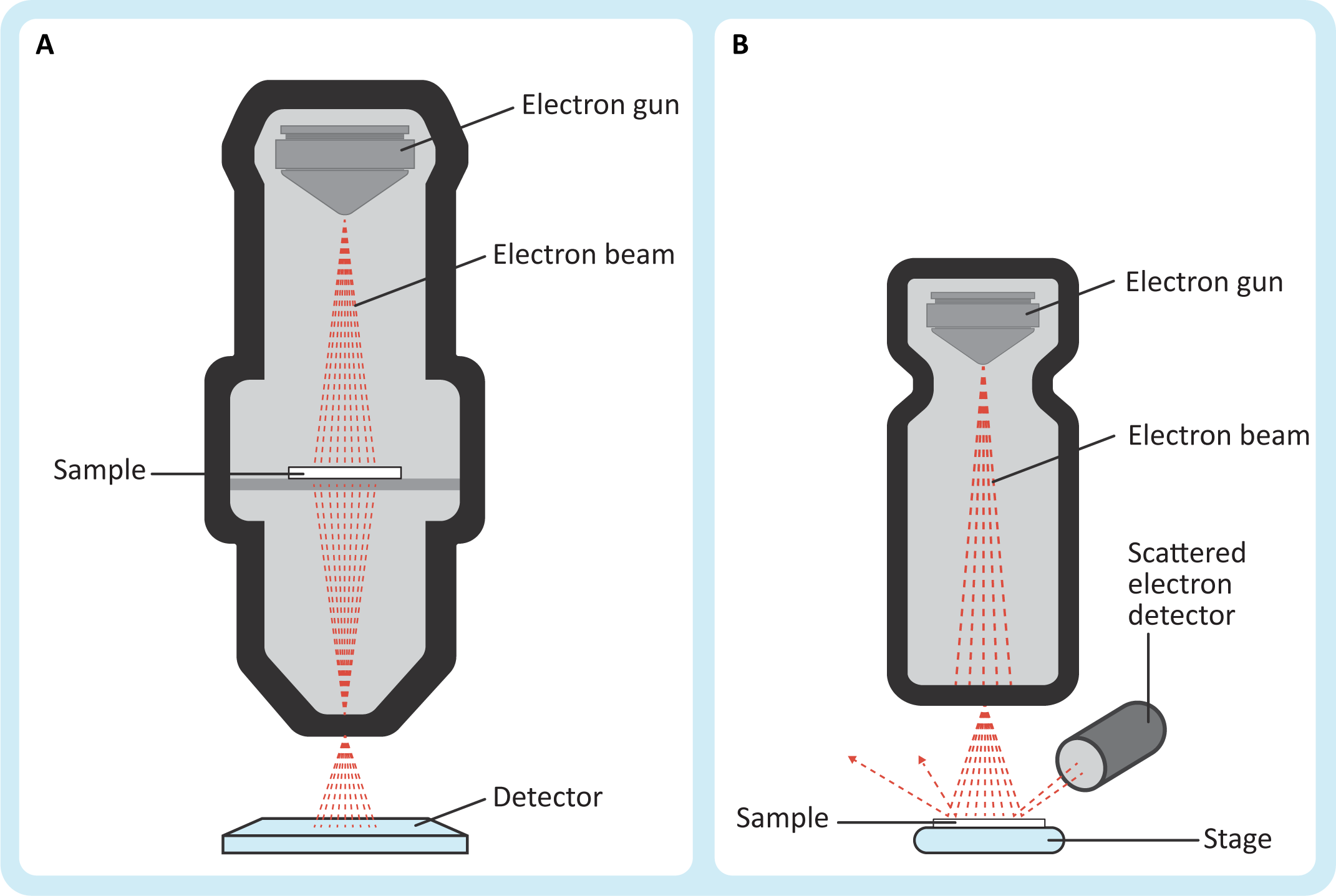
In many ways, TEM is analogous to traditional brightfield light microscopy, but with much greater capabilities with respect to magnification and resolution. The sample sits between the electron source and the detector (Figure 01-08A) so that the beam of electrons passes through the sample on its way to the detector. Just like in brightfield light micrographs, the empty spaces will show up as white in the image. Unlike light microscopy, there is no color in electron micrographs. Instead, the areas where the electrons were absorbed by the sample will be gray or black (depending on how “electron dense” your sample is in that region).
In TEM, the electron beam passes through the specimen. Electrons cannot penetrate very deeply, so the specimen must be extremely thin. The specimens are typically 50–100 nm sections of cells that have first been stained with heavy metals and then embedded in plastic resin. As you can imagine, all of this sample processing, along with the fact that the inside of a TEM is a vacuum, means that TEM cannot be used with living material. Instead, samples are carefully preserved, prior to embedding in epoxy resins, by either flash freezing (also known as cryofixation ) or using chemical fixatives. If we do this carefully enough, we can capture cellular events that were happening at the moment of fixation. Being gentle with samples so as to avoid disturbing the location of each and every molecule while also removing water and replacing it with epoxy resin is very difficult, which is why this process can take days, weeks, or even months.
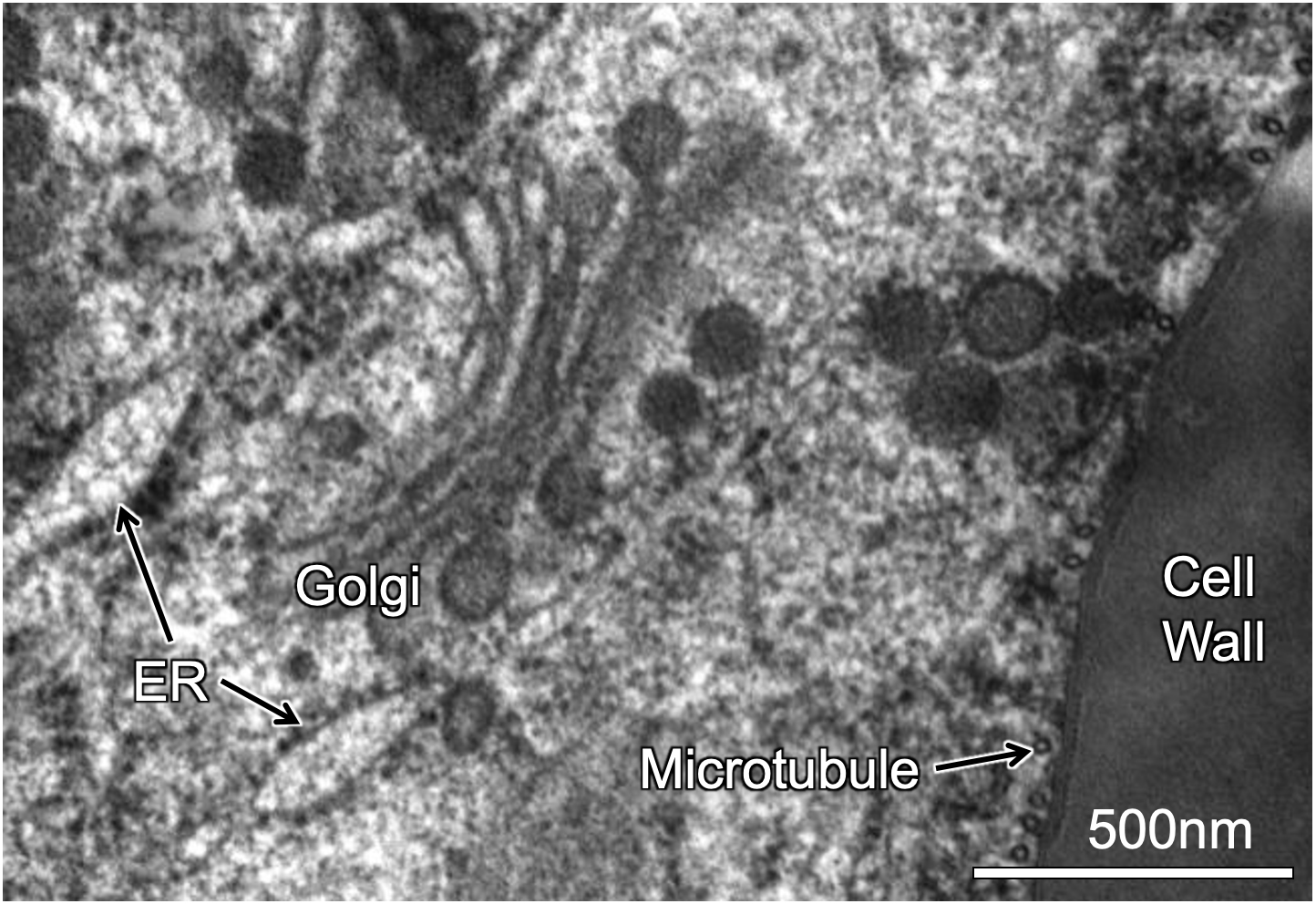
The electrons that have passed through the specimen are collected by an electron detector attached to a digital camera. An example is shown in Figure 01-08, where some of the subcellular structures in a plant cell have been labeled for you.
Much like in light microscopy, samples must be stained so that the structures are visible. As mentioned, we use heavy metal stains for electron microscopy. This is because of how electrons are able to move in heavy metal atoms. Heavy metals like lead (Pb), uranium (U), osmium (Os), gold (Au), and silver (Ag) are considered to be more “electron dense” and thus will be better able to block the electron beam than the atoms biological samples are made of, primarily carbon (C), oxygen (O), and hydrogen (H). We are also able to use immunolabeling in TEM in order to identify the location of specific proteins. However, we use colloidal gold particles of a specific size, rather than any kind of fluorescent tag, that are attached to antibodies that recognize our structure or protein of interest.
Negative staining is another technique that is most commonly used to examine very small objects, such as bacteria, viruses, and even individual proteins. In this technique the sample is suspended in an electron-dense stain that does not penetrate the sample but rather surrounds it so that it is outlined and all of the cracks and crevices can be observed.
Scanning Electron Microscopy (SEM)
In SEM, the specimen is usually dried and coated with a very thin layer of gold, platinum, or another heavy metal. The electron beam is “scanned” across the surface of the specimen. As the beam of electrons hits the specimen, secondary electrons are scattered from the surface of the specimen (Figure 01-08B). These are collected by a detector that builds an image electronically based on electron intensity (from white to black). This technique produces images of surfaces only. Since this microscope also uses electrons to image, the magnification and resolution are similar to TEM.
While samples are usually dead, when imaged with SEM, they do not have to be embedded in plastic like they are for TEM. Panels B and C of Figure 01-09 are of material that was cryofixed and imaged in the frozen state.

Topic 1.4: Putting It into Practice: Determining the Type of Microscopy from the Micrograph
- Interpret the results in experiments using microscopy based on scale, magnification, resolution, and plane of section.
- Identify the type of microscopy that is best suited to detect and study cellular components based on their size and the functional aspect being studied.
One of the major skills you should be practicing as you learn about cell biology is how to interpret micrographs. This is not a trivial skill to learn. However, the very first step in this process is being able to identify the type of microscopy that was used based solely on the image.
When you look at a micrograph of any kind, there are a number of questions that you should be asking yourself, including the following:
- What is the magnification/scale of the image? Can I find a scale bar or other information to help me tell?
- Does the image look three-dimensional? Is there depth to the image?
- Is there a black background? Does the sample look like only some of the structures in the sample are visible?
- What types of structures do I think I can see? Does that match with the magnification/resolution I would expect based on the type of microscopy?
- Is it in color? Does the color look like it might be computer-generated after the fact?
- Is it moving? Does it look like it could have been imaged live?
- Finally, what other information do I have about this image? Is there a figure legend or other text associated with the image that provides insight? It is quite common to place additional information in the text associated with the image, as we have done in this textbook chapter. Any information that you have about an image is there for you to use, so don’t forget to use it!
There is no single question in this list that can determine definitively what kind of microscopy was used. However, a combination of answers could help you make a reasonable decision, or at least a solid guess, based on the evidence. And every time you look at a new image, you’re going to have to figure it out again.
Light versus Electron Microscopy and the Question of Scale
While the size of what you’re looking at can be an important indicator of what type of microscopy you’re looking at, it’s also important to realize that more than one type of microscopy can often be used at any given magnification. We have repeated Figure 01-02 below because it does such a good job of visualizing the overlap and also to facilitate the discussion we’re about to have. It’s important to know what you can reasonably see in each type of microscopy so that you can make appropriate predictions about the information within the micrographs that you’re interpreting.
It is common when learning to identify microscopy from images to assume that anything imaged at a lower magnification is taken with a light microscope and anything at a higher magnification must be electron microscopy. However, that is not necessarily the case. Notice in Figure 01-02 that there is quite a lot of overlap in the range of light and electron microscopy. Other than the most extreme ends of very low magnification (like whole tissues, with many cells visible) and very high magnifications (like individual ribosomes), either type of microscopy can be used. This means that you need to take into consideration more than just the magnification . As we mentioned at the beginning of this chapter, resolution is also extremely important. For example,
- If you are using a light microscope at very high magnifications, you may be able to see bacteria (like E. coli as shown in the figure), but you won’t be able to see much of the details of the cytosol.
- On the other hand, at the same magnification, an electron microscope would likely allow you to see much more fine detail. You would likely be able to identify the location of the nucleoid and see some of the details of the flagella and their attachment to the plasma membrane.
Brightfield versus Transmission Electron Microscopy (TEM)
We have also found that it can be quite challenging for students to differentiate between a lower-magnification TEM image and a higher-magnification brightfield image. Video 01-01, posted earlier in this chapter, does an excellent job of explaining this, so we would encourage you to watch that video if you haven’t already. However, here are some things to consider that might help you to tell the difference:
- Brightfield microscopy allows for much lower magnification images than TEM does. At best, a low-magnification TEM image would only allow you to see two or three cells, so if you can see more than that, it’s probably brightfield.
- Similarly, TEM allows for much higher magnification images, so if you’re seeing only a small subsection of the cell’s cytoplasm in great detail, it’s probably TEM.
- If you can see a whole cell, or even a large part of a cell, it could be either TEM or brightfield, so here you need to think about resolution. TEM will show much more of the finer details of the cytoplasm, and many of the organelles will likely be identifiable. Brightfield is more likely to show you a bunch of fuzzy blobs inside the cell, and you may not be able to tell what they all are.
- Any technique that uses light microscopy has the potential to produce color images, so that could be something to consider as well, but cautiously. Remember that color is exceptionally easy to manipulate in digital images, and it can be added and removed at will. Also, if you are working to identify micrographs on a paper exam, it will most likely be printed in black and white, so you may or may not have the information about color in the image you are analyzing.
Scanning Electron Microscopy (SEM) versus Fluorescence Microscopy
With the advances in fluorescence microscopy and the ability to digitally reconstruct a stack of images into a single 3D image, it can also be challenging to tell the difference between images created by these two types of microscopes.
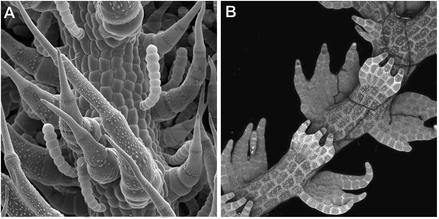
The key difference is that in SEM, you can only ever see the surface of the sample. (Compare Panels A and B from Figure 01-10.) In Figure 01-10A, we have an SEM image, which shows the surface structure of a leaf. Only the surface of the leaf cells is visible and nothing else. On the other hand, in fluorescence microscopy, the sample itself is emitting the light that you are viewing. This means that anything that is emitting light will be visible, whether it’s an internal structure or a surface element. In Figure 01-12B, it looks as if the cells are little compartments with dots in them. The dots are the chloroplasts inside the cell, emitting light. So even though this image looks 3D, we can still see beyond the surface of the sample, into the interior of the cells. Sometimes in SEM, the tissue is cracked open, so the inside of the cells is visible. (See Figure 01-12C for an example.) However, it is still very clear that it is the surface of the sample that’s being viewed in SEM, even though that surface is from the interior of the cell.
One additional thing to look for is the “quality” of the blackness of the background (when visible). In fluorescence, since the light is being emitted by the sample, the background will be very black, with no defining features. In SEM, however, the electrons are bounced off the surface of the sample, so there’s more likely to be some depth or texture to the background, even when it’s very dark/black. This may be subtle, but when visible it gives a useful clue.
Of course, none of these tricks work 100% of the time. The technology we have developed for imaging is very good, and the differences between them are getting smaller. There are times when it can be impossible to tell. In those cases, there are still options. In these cases, we encourage you to take your best guess based on the evidence you have. Sometimes that is all you can really do, and then you can see where the rest of the conversation takes you.
Chapter Summary
Microscopes are arguably the most essential tool to study cell biology. Virtually everything we study in cell biology is far too small to see with the naked eye. There have been some pretty significant advances in microscope technology, especially in the last 100 years. Here we break down the different forms of microscopy into the following:
- emitted light microscopy, represented by the brightfield light microscope
- transmitted light microscopy, represented by the fluorescent light microscope
- transmission electron microscopy (TEM)
- scanning electron microscopy (SEM)
Each one has different capacities in terms of magnification and resolution, both of which are key to determining what you should expect to see with each of these microscopes. It’s important to remember that the bulk of cell biology is within a size range that allows both light and electron microscopy to be used, so it’s important to consider how much detail you can see (i.e., the resolution), as well as the magnification and other parameters, when trying to decide how a sample was imaged.
Review Questions
Note on usage of these questions: Some of these questions are designed to help you tease out important information within the text. Others are there to help you go beyond the text and begin to practice important skills that are required to be a successful cell biologist. We recommend using them as part of your study routine. We have found them to be especially useful as talking points to work through in group study sessions.
- What determines the resolution of a microscope? Why is resolution more important at higher magnifications?
- Particle used to image (i.e., photons versus electrons)
- Path of particle through the microscope to produce the image (Can you make a rough sketch?)
- Sample preparation (Should samples be alive or dead? Stained or unstained? Any other unique characteristics of each one?)
- Major advantages and disadvantages of each kind of microscopy
- Tips and tricks for recognizing images produced by each type of microscopy that will help you on your exams
- Practice interpreting micrographs! Find a really good website that showcases micrographs that were imaged using a variety of microscopes (an exceptionally good one is www.cellimagelibrary.org , but there are others as well). Then use that website to practice interpreting micrographs and identifying cellular features. Try to find examples of the same structure that has been imaged using different types of microscopes and using different staining techniques.
- Identify the type of microscopy that is best suited to detect and study cellular components based on their size and functional aspect being studied.
- How do different staining techniques (i.e., immunolabeling, negative staining, etc.) help you visualize your sample?
- What are the advantages of using green fluorescent protein (GFP) instead of more traditional immunofluorescent staining techniques? How does it work?
“The simplest of all the optical microscopy illumination techniques. Sample illumination is transmitted (i.e., illuminated from below and observed from above) white light, and contrast in the sample is caused by attenuation of the transmitted light in dense areas of the sample.” Source: Bright-field microscopy. (2023, May 8). In Wikipedia, The Free Encyclopedia . https://en.wikipedia.org/wiki/Bright-field_microscopy
A microscopy technique where samples are illuminated with light of a particular wavelength. The fluorescent molecules in the sample become excited and emit light of a longer wavelength. The microscope catches this light to display the location of the fluorescent molecules bound to a cellular structure of interest. There are two main types of fluorescent light microscopy: epifluorescence and confocal microscopy.
“Transmission electron microscopy (TEM) is a microscopy technique in which a beam of electrons is transmitted through a specimen to form an image. The specimen is most often an ultrathin section less than 100 nm thick or a suspension on a grid. An image is formed from the interaction of the electrons with the sample as the beam is transmitted through the specimen.” Source: Transmission electron microscopy. (2023, June 2). In Wikipedia, The Free Encyclopedia . https://en.wikipedia.org/wiki/Transmission_electron_microscopy
“A type of electron microscope that produces images of a sample by scanning the surface with a focused beam of electrons.” Source: Scanning electron microscope. (2023, July 17). In Wikipedia, The Free Encyclopedia . https://en.wikipedia.org/wiki/Scanning_electron_microscope
Refers to enlarging the apparent size of an image. This is akin to scaling or zooming in on an image and does not change its inherent resolution.
“Quantifies how close lines can be to each other and still be visibly resolved. Resolution units can be tied to physical sizes (e.g., lines per mm, lines per inch), to the overall size of a picture (lines per picture height, also known simply as lines, TV lines, or TVL), or to angular subtense.” Source: Image resolution. (2023, June 2). In Wikipedia, The Free Encyclopedia . https://en.wikipedia.org/wiki/Image_resolution
“A series of techniques in optical microscopy that allow such images to have resolutions higher than those imposed by the diffraction limit, which is due to the diffraction of light.” Source: Super-resolution microscopy. (2023, May 25). In Wikipedia, The Free Encyclopedia . https://en.wikipedia.org/wiki/Super-resolution_microscopy
“An optical microscopy technique that converts phase shifts in light passing through a transparent specimen to brightness changes in the image.” Source: Phase-contrast microscopy. (2023, July 17). In Wikipedia, The Free Encyclopedia . https://en.wikipedia.org/wiki/Phase-contrast_microscopy
“Describes microscopy methods, in both light and electron microscopy, which exclude the unscattered beam from the image. As a result, the field around the specimen (i.e., where there is no specimen to scatter the beam) is generally dark.” Source: Dark-field microscopy. (2022, September 7). In Wikipedia, The Free Encyclopedia . https://en.wikipedia.org/wiki/Dark-field_microscopy
A subset of transmitted light microscopy where polarized light is used to enhance the contrast of the image. DIC (differential interface contrast) microscopy is one common example of this technique.
The most general ubiquitous form of fluorescence light microscopy. Light at the excitation wavelength is applied to the sample. Then the detector will pick up the emission wavelength of light emitted from the sample.
Uses a laser to excite fluorescent molecules inside cells, similar to epifluorescence. However, the light shines through a pinhole to block out-of-focus light. This allows for “optical” sectioning (dividing the cells) along an axis and can result in a sharper image.
When colored or fluorescent dyes are added to a biological sample to help differentiate cellular structures under the microscope.
“A biochemical process that enables the detection and localization of an antigen to a particular site within a cell, tissue, or organ. Antigens are organic molecules, usually proteins, capable of binding to an antibody.” Source: Immunolabeling. (2023, February 9). In Wikipedia, The Free Encyclopedia . https://en.wikipedia.org/wiki/Immunolabeling
A naturally occurring protein found in jellyfish that glows green when excited with blue wavelength light. It is commonly fused genetically to proteins of interest to visualize the interior of cells.
The chemical gradient or difference in solute concentration across a membrane.
“A technique for fixation or stabilization of biological materials as the first step in specimen preparation for electron microscopy and cryo-electron microscopy.” Source: Cryofixation. (2023, May 27). In Wikipedia, The Free Encyclopedia . https://en.wikipedia.org/wiki/Cryofixation
“An established method, often used in diagnostic microscopy, for contrasting a thin specimen with an optically opaque fluid. In this technique, the background is stained, leaving the actual specimen untouched, and thus visible.” Source: Negative stain. (2021, December 4). In Wikipedia, The Free Encyclopedia . https://en.wikipedia.org/wiki/Negative_stain
Fundamentals of Cell Biology Copyright © 2024 by Lauren Dalton and Robin Young is licensed under a Creative Commons Attribution-NonCommercial 4.0 International License , except where otherwise noted.
Exercise 1: Using a Compound Microscope
- First Online: 02 August 2021
Cite this chapter

- Tobili Y. Sam-Yellowe 2
2539 Accesses
The compound microscope is one of the most important instruments found in laboratories engaged in the examination of cells and microorganisms. We will examine mouse blood stained with Giemsa stain to identify red blood cells (erythrocytes), white blood cells (leukocytes) and platelets (thrombocytes). Some of the red cells are infected with Plasmodium yoelii and P. berghei , intracellular parasites within the red cells, and causative agents of rodent malaria. The parasites are protozoans, eukaryotic cells and therefore the nucleus and cytoplasm will be stained. Uninfected erythrocytes lack a nucleus and will be stained red/pink. The objectives of the introductory exercise are to: (1) Review parts and function of a compound microscope; (2) Review calculation of magnification and (3) Identify uninfected erythrocytes, Plasmodium infected erythrocytes, leukocytes and platelets. A differential count of the leukocytes will be performed to determine the percentage of each leukocyte in the blood smear.
This is a preview of subscription content, log in via an institution to check access.
Access this chapter
- Available as EPUB and PDF
- Read on any device
- Instant download
- Own it forever
- Compact, lightweight edition
- Dispatched in 3 to 5 business days
- Free shipping worldwide - see info
- Durable hardcover edition
Tax calculation will be finalised at checkout
Purchases are for personal use only
Institutional subscriptions
Author information
Authors and affiliations.
Cleveland State University, Cleveland, OH, USA
Tobili Y. Sam-Yellowe
You can also search for this author in PubMed Google Scholar
Rights and permissions
Reprints and permissions
Copyright information
© 2021 Springer Nature Switzerland AG
About this chapter
Sam-Yellowe, T.Y. (2021). Exercise 1: Using a Compound Microscope. In: Immunology: Overview and Laboratory Manual. Springer, Cham. https://doi.org/10.1007/978-3-030-64686-8_25
Download citation
DOI : https://doi.org/10.1007/978-3-030-64686-8_25
Published : 02 August 2021
Publisher Name : Springer, Cham
Print ISBN : 978-3-030-64685-1
Online ISBN : 978-3-030-64686-8
eBook Packages : Biomedical and Life Sciences Biomedical and Life Sciences (R0)
Share this chapter
Anyone you share the following link with will be able to read this content:
Sorry, a shareable link is not currently available for this article.
Provided by the Springer Nature SharedIt content-sharing initiative
- Publish with us
Policies and ethics
- Find a journal
- Track your research

- school Campus Bookshelves
- menu_book Bookshelves
- perm_media Learning Objects
- login Login
- how_to_reg Request Instructor Account
- hub Instructor Commons
Margin Size
- Download Page (PDF)
- Download Full Book (PDF)
- Periodic Table
- Physics Constants
- Scientific Calculator
- Reference & Cite
- Tools expand_more
- Readability
selected template will load here
This action is not available.

1.3: Lab Report
- Last updated
- Save as PDF
- Page ID 103125
\( \newcommand{\vecs}[1]{\overset { \scriptstyle \rightharpoonup} {\mathbf{#1}} } \)
\( \newcommand{\vecd}[1]{\overset{-\!-\!\rightharpoonup}{\vphantom{a}\smash {#1}}} \)
\( \newcommand{\id}{\mathrm{id}}\) \( \newcommand{\Span}{\mathrm{span}}\)
( \newcommand{\kernel}{\mathrm{null}\,}\) \( \newcommand{\range}{\mathrm{range}\,}\)
\( \newcommand{\RealPart}{\mathrm{Re}}\) \( \newcommand{\ImaginaryPart}{\mathrm{Im}}\)
\( \newcommand{\Argument}{\mathrm{Arg}}\) \( \newcommand{\norm}[1]{\| #1 \|}\)
\( \newcommand{\inner}[2]{\langle #1, #2 \rangle}\)
\( \newcommand{\Span}{\mathrm{span}}\)
\( \newcommand{\id}{\mathrm{id}}\)
\( \newcommand{\kernel}{\mathrm{null}\,}\)
\( \newcommand{\range}{\mathrm{range}\,}\)
\( \newcommand{\RealPart}{\mathrm{Re}}\)
\( \newcommand{\ImaginaryPart}{\mathrm{Im}}\)
\( \newcommand{\Argument}{\mathrm{Arg}}\)
\( \newcommand{\norm}[1]{\| #1 \|}\)
\( \newcommand{\Span}{\mathrm{span}}\) \( \newcommand{\AA}{\unicode[.8,0]{x212B}}\)
\( \newcommand{\vectorA}[1]{\vec{#1}} % arrow\)
\( \newcommand{\vectorAt}[1]{\vec{\text{#1}}} % arrow\)
\( \newcommand{\vectorB}[1]{\overset { \scriptstyle \rightharpoonup} {\mathbf{#1}} } \)
\( \newcommand{\vectorC}[1]{\textbf{#1}} \)
\( \newcommand{\vectorD}[1]{\overrightarrow{#1}} \)
\( \newcommand{\vectorDt}[1]{\overrightarrow{\text{#1}}} \)
\( \newcommand{\vectE}[1]{\overset{-\!-\!\rightharpoonup}{\vphantom{a}\smash{\mathbf {#1}}}} \)
Exercise 1: Identifying the parts of the microscope

Figure \(\PageIndex{1}\): Side and front view of Olympus CX43 microscope, from user manual.
Identify & label the following parts of your microscope onto the image above, and fill-in-the blanks below.
· Binocular head, Oculars: _______x
· Arm
· Revolving nosepiece
· Objective lenses: ______x, _______x, _______x, _______x
· Mechanical stage and X/Y knobs
· Stage/slide clips
· Condenser Turret __________, ___________, __________, ____________
· Iris diaphragm and how to adjust it
· Coarse adjustment knob & fine adjustment knob
· Light source; illuminator
· Base
· Dimmer; light intensity
· Power switch & power cord
· Total magnification calculation =
Exercise 2: Using your Microscope
View both Paramecium and Amoeba slides under the 4x, 10x, and 40x objectives, and sketch and label each organism in the space below. Do NOT use the oil immersion lens today.
- Pick 1-3 cells of each organism to draw.
- You decide which magnification is best for each specimen. For example, a larger cell/specimen might best be seen with the 10x objective instead of the 40x objective.
- Make sure to label each sketch with the organism’s name, the total magnification, the calculation for total magnification, and label distinguishing features of the organism. For example, for Amoeba label the nucleus and pseudopod(s).

Microscopes & Lab Safety Review Questions
After reading the safety guidelines (see appendix) and the microscope introduction, answer the following questions.
1. It is okay to drink bottled water in the lab.
2. Which type of shoes must students wear in the laboratory?
b. Shoes with non-slip tread/soles
c. Any type of shoe
d. Shoes that cover your entire foot
3. The classroom fire extinguishers are located near the
a. Staff entrance
b. Student exits
c. Steel sink
d. Teacher’s desk
4. The classroom phone is located at the
5. Guests are allowed in lab if they have prior permission and have agreed to the laboratory safety rules.
6. During an emergency evacuation, we should meet at
a. Student Lot 9 (near observatory entrance)
b. The Sequoia / Valle Del Lago roundabout
c. Montgomery Hill Observatory
d. Staff Parking Lot 7
7. While viewing a microscope slide, you find that the light appears too dim for your preference. Adjustment of which of the following might solve your problem?
b. Course adjustment knob
c. Iris diaphragm
d. Stage clips
8. It is okay to use soft Kleenex to clean your microscope lenses.
9. Once you have a slide in focus under one of the lenses, the other lenses will be in focus as well and therefore will only require slight adjustment using the fine focus knob. This is because our microscopes are ___________.
a. Expensive
c. Parfocal
d. Refractory
10. We must (always and only) use oil when viewing slides using which objective lens?
11. It is best to always begin viewing a slide using the 40x objective lens.
12. When focusing a slide, the stage should be all the way ____ before you look through the oculars.
13. When storing the microscope, the stage should be ____, and the ____ objective lens should be centered (in front).
c. Down, 4x
d. Down, 40x
14. True or False: Before and after each use with the microscope, you should clean the objective lenses, starting with the 4x objective.
15. We never drag the microscope across the bench top because
a. The sound it makes is irritating
b. The Professor will have a fit
c. This loosens and/or damages the parts of the microscope
16. Before and after each lab, you should
a. Wipe down bench tops and chair
b. Clear sinks, bench tops, and floors of any trash/debris
c. Push in your chair
- Types Of Microscope
Types of Microscopes
What are the different types of microscopes.
There are different types of microscopes and each of these has different purposes of use. Some are suitable for biological applications, while others are used in educational institutions. There are also microscope types that find application in metallurgy and studying three-dimensional samples.
In this article, there are 5 such microscope types that are discussed along with their diagram, working principle and applications. These five types of microscopes are:
- Simple microscope
- Compound microscope
- Electron microscope
- Stereomicroscope
- Scanning probe microscope
Simple Microscope
A simple microscope is defined as the type of microscope that uses a single lens for the magnification of the sample. A simple microscope is a convex lens with a small focal length. The magnifying power of the simple microscope is given as
- D is the least distinct vision
- F is the focal length of the convex lens
Simple Microscope Diagram

Principle of Simple Microscope
The working principle of a simple microscope is that when a sample is placed within the focus of the microscope, a virtual, erect and magnified image is obtained at the least distance of distinct vision from the eye that is held at the lens.
Application of Simple Microscope
- It is common among the watchmakers as they can view a magnified image of the smallest parts.
- It is also used by the jewellers for obtaining a magnified image of the fine parts of the jewellery.
- Most educational institutions such as schools and colleges use a simple microscope in their laboratories.
- Dermatologists (skin specialists) use simple microscopes to identify different skin diseases.
Compound Microscope
A compound microscope is defined as the type of microscope that has more than one lens. It has a combination of lenses and two optical parts known as an objective lens and an eyepiece or ocular lens. The magnifying power of the compound microscope is given as:
- D is the least distance of distinct vision
- L is the length of the microscope tube
- f o is the focal length of the objective lens
- f e is the focal length of the eyepiece
Compound Microscope Diagram

Principle of Compound Microscope
The working principle of the compound microscope is that the combination of lenses enhances the magnification of the sample. The sample is first viewed as a primary image in the tube and viewed again in the eyepiece.
Applications of Compound Microscope
- The study of bacteria and viruses is possible with the help of a compound microscope.
- A compound microscope finds application in forensic laboratories.
- It is also used in metallurgy.
Electron Microscope
An electron microscope is defined as the type of microscope in which the source of illumination is the beam of accelerated electrons. It is a special type of microscope with a high resolution of images as the images can be magnified in nanometers.
There are two types of electron microscopes:
- The transmission electron microscope (TEM)
- The scanning electron microscope (SEM)

Principle of Electron Microscope
The metal used in an electron microscope is tungsten. A high voltage current is applied which results in the excitation of the electrons in the form of a continuous stream that is used as a beam of light. The lenses used in the electron microscope are magnetic coils. These magnetic coils are capable of focusing the electron beam on the sample such that the sample gets illuminated. As the flow of current increases, the strength of the magnetic lens increases. The electron beam flow is designed such that it cannot pass through the glass lens.
Application of Electron Microscope
- Quality control and failure analysis in industries are done with the help of an electron microscope.
- The images obtained in an electron microscope can be captured as electron micrographs with the help of specialized cameras.
- The study of metals and crystals became easy with the introduction of an electron microscope.
Stereo Microscope
A stereo microscope is defined as a type of microscope that provides a three-dimensional view of a specimen. It is also known as a dissecting microscope. In a stereo microscope, there are separate objective lenses and eyepiece such that there are two separate optical paths for each eye.
Stereo Microscope Diagram

Principle of Stereo Microscope
A stereo microscope works on the reflected light from the sample. The magnification of the microscope takes place at low power and hence, it is suitable for magnifying opaque objects. It is suitable for thick and solid samples because it uses light reflected from the sample. The magnification of the stereo microscope is between 20x and 50x.
Applications of Stereo Microscope
- Examination of historic coins and artefacts is possible with the help of the stereomicroscope.
- It finds application in microsurgery.
- Viewing of crystals became easy with the use of a stereomicroscope.
Scanning Probe Microscope
The scanning probe microscope is defined as the type of microscope that finds applications in industries where the examination of the specimen is done at the nanoscale levels. The study of a specimen’s properties, its reaction time and its behaviour when stimulated can be done with the help of a scanning probe microscope.
Scanning Probe Microscope Diagram

Principle of Scanning Probe Microscope
The scanning probe microscope has a probe tip that is mounted on the end of a cantilever. The tip is so sharp that it can move precisely and accurately across the surface of the sample scanning every atom. The tip is placed close to the surface of the sample, such that the cantilever experiences a deflection due to forces. This deflection distance is measured by the laser. The final image after scanning is obtained on the computer.
Application of Scanning Probe Microscope
- It is used in studying different properties of the sample such as electrical properties.
- The magnetic property of the sample is studied using this microscope.
- The transferring of information on the sample can be done with the help of this microscope.
Related articles:
Frequently Asked Questions – FAQs
What is the difference between low-powered and high-powered microscopes.
The basic difference between low-powered and high-powered microscopes is that a high power microscope is used for resolving smaller features as the objective lenses have great magnification. However, the depth of focus is greatest for low powered objectives. As the power is switched to higher, the depth of focus reduces.
What is depth of focus in a microscope?
The depth of focus in a microscope is defined as the distance between the objective lens and the sample plane. The depth of focus varies from person to person and is also dependent on the quality of focus.
What is the depth of field in a microscope?
The depth of field in a microscope is defined as the distance from the nearest object plane in focus to the farthest plane in the same focus. In microscopes, the depth of field is very short and is measured in units of microns.
What is the field of view in a microscope?
The field of view in a microscope is defined as the diameter of the illuminated circle which is seen through the eyepiece. With an increase in the magnification, there is a decrease in the field of view.
What is diopter adjustment?
The difference in vision between the two eyes is corrected with the help of diopter adjustment. Through diopter adjustment, the focus of the individual eyepiece can be done so that the eyes feel comfortable while observing the sample.
Watch the video and learn more about lens formula

Stay tuned with BYJU’S to learn more about other concepts of Physics.

Put your understanding of this concept to test by answering a few MCQs. Click Start Quiz to begin!
Select the correct answer and click on the "Finish" button Check your score and explanations at the end of the quiz
Visit BYJU'S for all Physics related queries and study materials
Your result is as below
Request OTP on Voice Call
Leave a Comment Cancel reply
Your Mobile number and Email id will not be published. Required fields are marked *
Post My Comment
- Share Share
Register with BYJU'S & Download Free PDFs
Register with byju's & watch live videos.


IMAGES
VIDEO
COMMENTS
Compound Microscope: Principle, Parts, Uses, Diagram. March 28, 2024 by Prakriti Karki. Edited By: Sagar Aryal. Compound microscopes are built using a compound lens system where the primary magnification is provided by the objective lens, which is then compounded (multiplied) by the ocular lens (eyepiece). The objective lens is the lower lens ...
5. Switch the microscope to the next highest magnification objective (commonly 100x TOTAL magnification) and adjust the focus using the fine focus knob. 6. Count the number of spaces between the lines on the ruler to determine the length of the diameter of the field of view of the compound microscope. Record this length in the table below. 7.
A compound microscope is defined as. A microscope with a high resolution and uses two sets of lenses providing a 2-dimensional image of the sample. The term compound refers to the usage of more than one lens in the microscope. Also, the compound microscope is one of the types of optical microscopes. The other type of optical microscope is a ...
The optical system of a compound microscope consists of two lens systems: one found in the objective(s) lens(es) (Fig. 2, part 3); the other in the ocular (eyepiece) (Fig. 2 part 1). The objective lens system is found attached to a rotating nosepiece (Fig. 2, part 2). A microscope usually has three or four objectives that differ in their ...
Meaning. Simple microscope - It is a convex lens of small focal length and its primary use is to see a magnified image of small objects. Compound microscope - It is an optical instrument consists of two convex lenses of short focal lengths primarily used for observing a highly magnified image of minute objects. Lenses.
A compound microscope: Is used to view samples that are not visible to the naked eye. Uses two types of lenses - Objective and ocular lenses. Has a higher level of magnification - Typically up to 2000x. Is used in hospitals and forensic labs by scientists, biologists and researchers to study microorganisms. Invented in the late 16th century ...
Anatomy of a Compound Microscope. Figure 3.5.1 3.5. 1: Adapted from Compound Microscope by Sarah Greenwood via Wikimedia Commons. CC BY 4.0. As you look through the ocular lenses, rotate the coarse focus knob away from you until your specimen comes into focus. You are viewing your specimen at 40x its actual size.
let's explore compound microscopes we'll first understand the logic behind it and then we'll build it so let's say you were looking at a tiny amoeba with your naked eye will imagine this is your eye and your cornea and your islands are together over here the schematic okay now how big this amoeba looks to you really depends on the size of the image form in your retina and that depends on this ...
AN INTRODUCTION TO THE COMPOUND MICROSCOPE OBJECTIVE: In this lab you will learn the basic skills needed to stain and mount wet slides. You will also learn about magnification, resolution and the parts of the compound microscope. INTRODUCTION: The light microscope can extend our ability to see detail by 1000 times, so that we can
Magnification is a measure of how much larger a microscope (or set of lenses within a microscope) causes an object to appear. For instance, the light microscopes typically used in high schools and colleges magnify up to about 400 times actual size. So, something that was 1 mm wide in real life would be 400 mm wide in the microscope image.
The compound microscope is a magnifier of close objects with a high angular magnification, generally more than 30× 30 ×. It was invented by Zacharias Janssen in Middelburg in 1590 (this claim is disputed). The first element of the compound microscope is an objective (in Figure 3.8.1 3.8. 1 a simple positive lens) which makes a real, inverted ...
Microscope Parts and Functions With Labeled Diagram and Functions How does a Compound Microscope Work?. Before exploring microscope parts and functions, you should probably understand that the compound light microscope is more complicated than just a microscope with more than one lens.. First, the purpose of a microscope is to magnify a small object or to magnify the fine details of a larger ...
Compound Microscope. An object containing a fingerprint is kept 1.8 cm from the objective ( f o = 1.4 cm) of a compound microscope. The fingerprint is observed to be magnified 30 times. Find the magnification produced by the eyepiece lens alone. Note:Report your answer correct to two significant figures. Learn for free about math, art, computer ...
A compound light microscope is a type of light microscope that uses a compound lens system, meaning, it operates through two sets of lenses to magnify the image of a specimen. It's an upright microscope that produces a two-dimensional image and has a higher magnification than a stereoscopic microscope. It also goes by a couple of other names ...
The very first microscope was made in the mid-1600s by a British man named Robert Hooke. That microscope had a mirror to direct sunlight into the glass lenses of the microscope so that the sample could be viewed. Microscopes stayed more or less the same for the next 300 years, until the Industrial Revolution of the early 1900s.
Procedure. 1. Retrieve the microscope from the cabinet by holding the arm and base of the microscope to provide support. 2. Take the microscope to your bench and plug it into the outlet on the side of the bench (some lab benches will have the plugs in the center of the bench). 3.
Rachael Ford 9/5/2019 - 12/10/ BIO220 General Microbiology CE Fall- Bishop State Community College. I. Title: Learning How to Use a Compound Light Microscope II. Purpose: This laboratory experiment was done to give experience in using a compound light microscope and to properly test your abilities to use the full capacity of its functions and use it appropriately.
One hand should hold the microscope's arm and the other hand should support the base, as shown in Figure 1. Set it down away from the edge of the table. Always remember that a microscope is an expensive, precision instrument that should be handled carefully. 2. Plug the microscope in at your lab desk.
There are three structural parts of the microscope i.e. head, arm, and base. Head - The head is a cylindrical metallic tube that holds the eyepiece lens at one end and connects to the nose piece at other end. It is also called a body tube or eyepiece tube. It connects the eyepiece lens to the objective lens.
The most familiar type of microscope is the optical, or light, microscope, in which glass lenses are used to form the image. Optical microscopes can be simple, consisting of a single lens, or compound, consisting of several optical components in line. The hand magnifying glass can magnify about 3 to 20×. Single-lensed simple microscopes can ...
Exercise 1: Identifying the parts of the microscope. Figure 1.3.1 1.3. 1: Side and front view of Olympus CX43 microscope, from user manual. Identify & label the following parts of your microscope onto the image above, and fill-in-the blanks below. · Binocular head, Oculars: _______x. · Arm.
The microscope lens may be cleaned with any soft tissue. The microscope should be stored with the oil immeover the stage. rsionlens in position; When beginning to focus, the lowest powerlens should be used. When focusing, always focus towardthe specimen. A coverslip should always be used with wand oil lenses. et mounts and the high-power; 4.
A compound microscope finds application in forensic laboratories. It is also used in metallurgy. Electron Microscope. An electron microscope is defined as the type of microscope in which the source of illumination is the beam of accelerated electrons. It is a special type of microscope with a high resolution of images as the images can be ...