Network Guys
Share your knowledge!

How to use 802.1x/mac-auth and dynamic VLAN assignment
Hello guys! Today I want to show you how to secure your edge-switches with 802.1x and mac-authentication fallback in combination with HPE comware-based switches. The 802.1x protocol is used for network access control. For devices like printers, cameras, etc. we will use mac-authentication as a fallback. We will also use dynamic VLAN assignment for the connected ports.
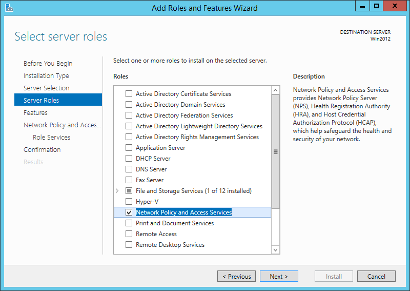
Our radius server will be Microsoft NPS. You can activate this role on the Windows server:
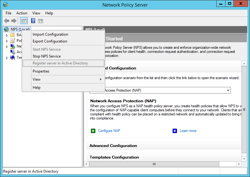
After the installation, open the NPS console and register the radius server in your Active Directory:
add your switches or your management network as a radius-client:
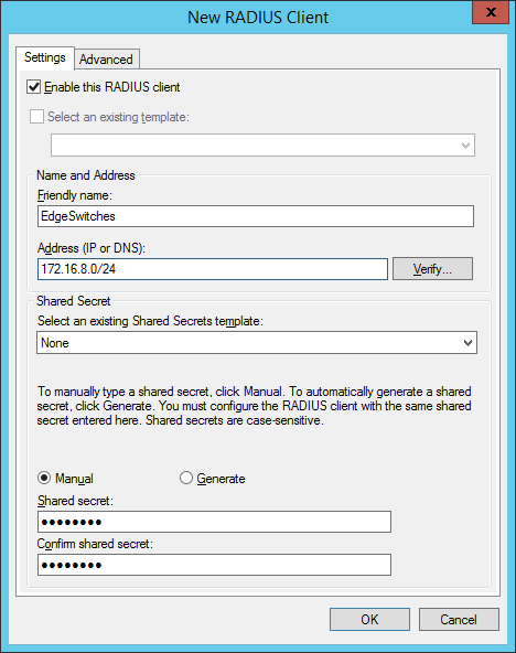
the shared secret will be used in the switch configuration. In created two groups within my test environment:
- “ VLAN2-802.1x ” containing computer accounts
- “ VLAN3-MAC-Auth ” containing user accounts (username+password = mac-address of the device)
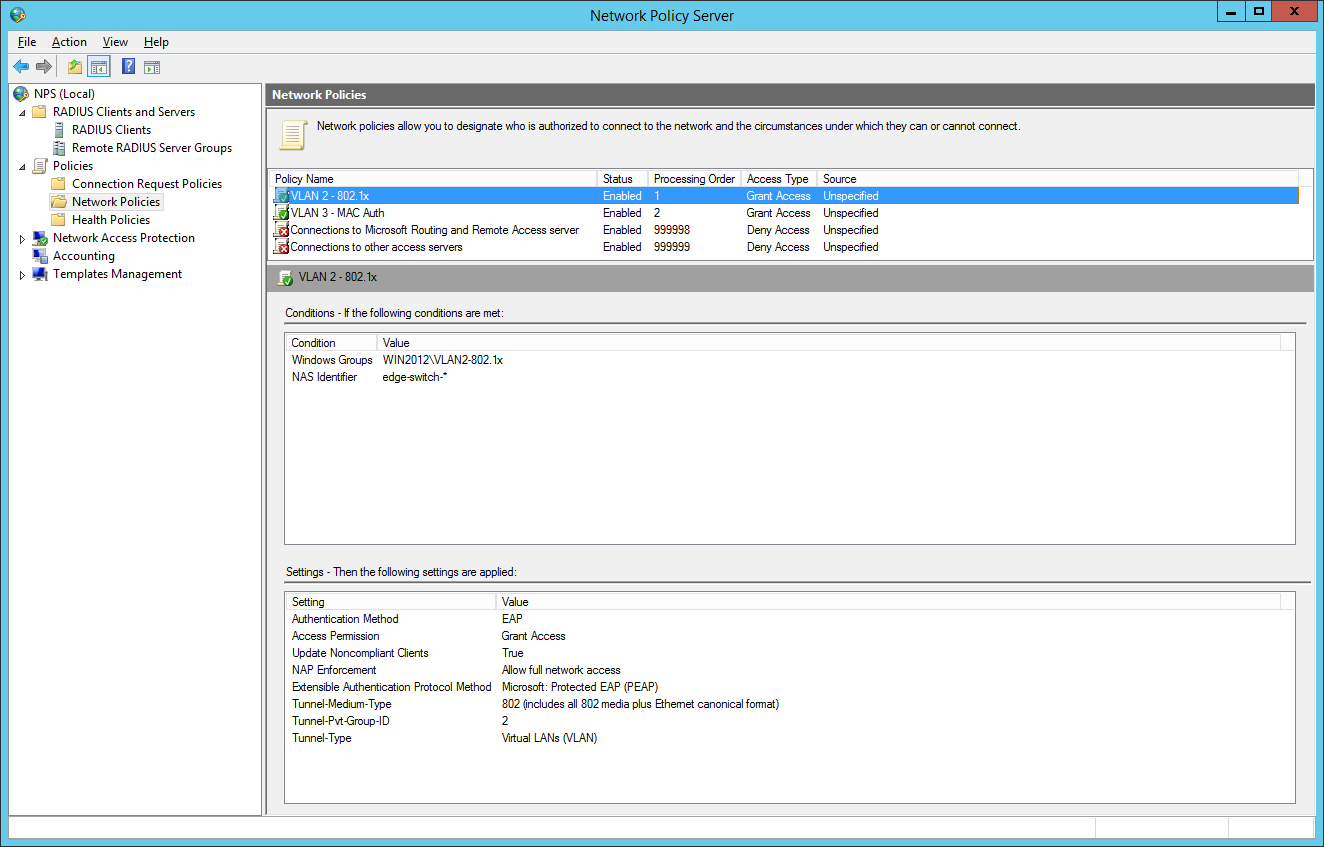
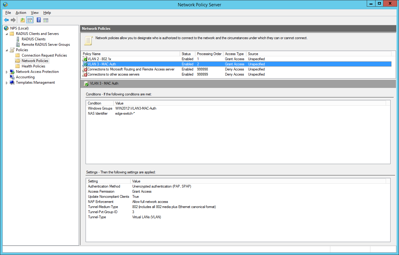
So we will now configure two network policies for our network access control:

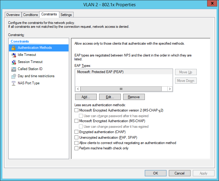
I also configured a NAS Identifier so no other device can use the radius server. The clients will use their computer certificate so you will need a running internal certification authority. Choose PEAP only as the authentication method:
the next step is for our dynamic VLAN assignment. Dot1x devices are bound to VLAN 2:
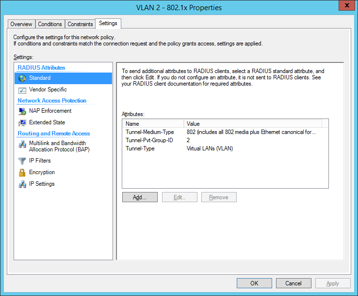
the final dot1x configuration in the NPS:
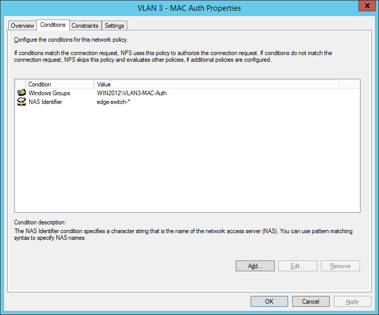
the second network policy is for the mac-based authentication:
Comware switches are sending MAC-Auth-requests via PAP (maybe you know how to change it to CHAP):
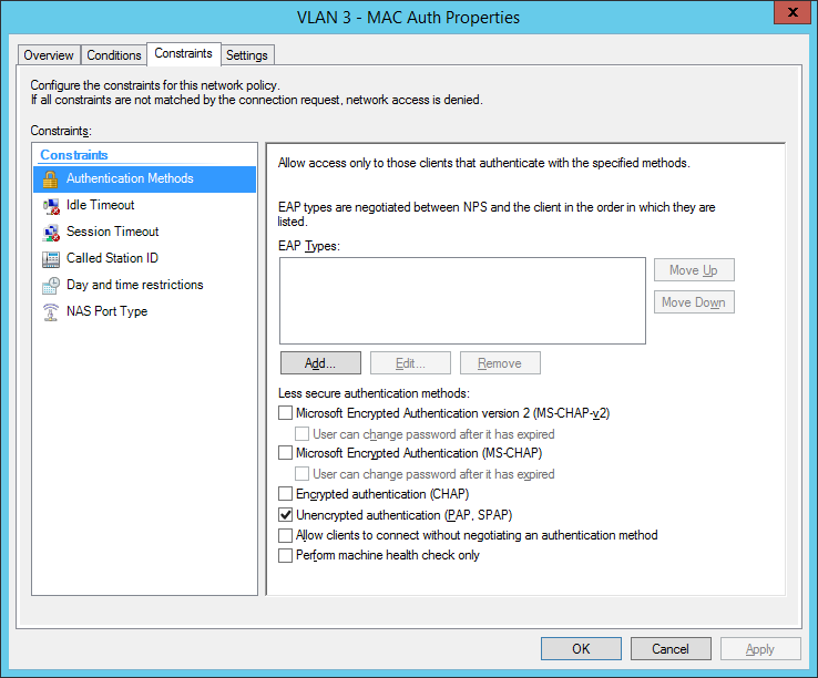
final MAC auth profile:
for now we have built up our authentication server. Now let’s go to the switch configuration. You have global configuration parameters and parameters for each interface. The best way is to use interface-range command to be safe at your configuration. Users who cant authenticate, will be forced to VLAN 999 (quarantine VLAN with no gateway). Here are the global parameters with explanations inline:
now we will configure the interfaces: Added 2 entries
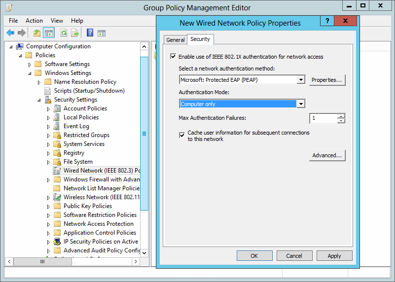
the last part is to configure all windows clients to send 802.1x auth data to the cable network. I’ve done this via a global group policy. You can find the settings under Computer Configuration / Policies / Windows Settings / Security Settings / Wired Network (IEEE 802.3) Policies:
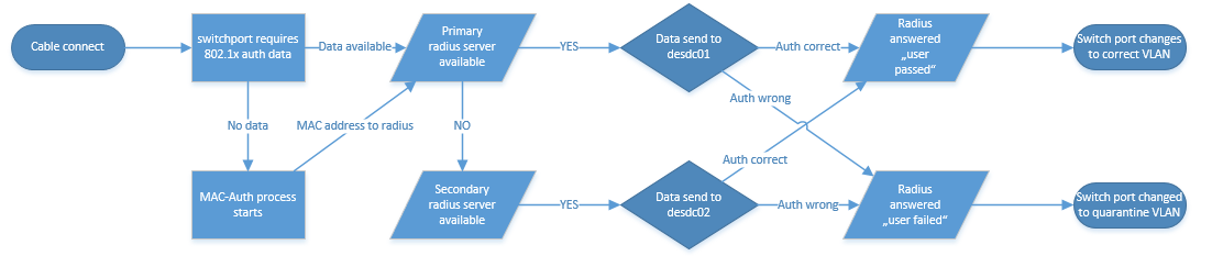
So how does a working 802.1x-auth looks like?
%Jan 3 01:59:59:531 2013 edge-switch-01 DOT1X/6/DOT1X_LOGIN_SUCC: -IfName=GigabitEthernet1/0/10-MACAddr=0023-2415-42a3-AccessVLANID=1- AuthorizationVLANID=2 -Username= host/PC123.mycompany.local ; User passed 802.1X authentication and came online.
Successful Mac-Authentication of a printer:
%Jan 3 01:31:28:782 2013 de-pad-l19-edg01 MACA/6/MACA_LOGIN_SUCC: -IfName=GigabitEthernet1/0/9-MACAddr=0017-c82d-e9bf-AccessVLANID=1- AuthorizationVLANID=3 -Username= 0017c82de9bf -UsernameFormat=MAC address; User passed MAC authentication and came online.
I tried to draw a flow chart which shows the authentication process, I hope it’s ok for you :)
Do you have questions? Feel free to write them into the comments and I will try to answer.
Have a nice and sunny day!
/edit: If you can’t see success and failure events, follow this instruction: NPS / Radius Server is not logging
/edit 2018-05-14: I corrected the global and interface configuration, we had problems with the old configuration
12 Responses
Thanks for this, I need to setup dynamic VLAN assignment in the near future but for Juniper equipment.
This at least gives me a good starting point, thanks for the write up.
Many thanks for the perfect tutorial on How to use 802.1x/Mac-Auth and dynamic VLAN assignment. Many of us can take help from it. Really nice.
Nice write-up. This was a great starting point for configuring the base for dynamic polices. Thanks!
hi Mike, how ‘s about hybrid port with voice-vlan? does it work?
thanks Tung Duong
we had several problems with this config, currently we are investigating hyprid ports with “port security” command. I will update this post if we have prooved this version.
Can you tell me why I would do this over conventional static VLANs? What are the benefits radius dynamic VLANs?
we have customers which want to divide the network for clients, printers and “special devices”. So you have different group/radius-policies to directly place the devices in the right VLAN. Dynamic VLAN is only a bonus feature which you can use. Of course, you can use only the 802.1x and Mac authentication for security purpose.
I’m on the desktop side of things, so apologies if I use any incorrect terminology here.
Our Infrastructure team are looking at introducing 8021x in our schools. They have a test setup where all 8021x devices pick up a data centre VLAN regardless of which building they’re in – eg 10.100.50.
Each building WIRED has its own unique IP – SchoolA=10.120, SchoolB = 10.130 and so on.
I’ve asked if the 8021x setup can be where 8021x devices in SchoolA will get 10.120.50; SchoolB will get 10.130.50
This would allow us to easily determine which building LaptopA actually is, in the same way as we can with our wired desktops. It also saves on SCCM boundary issues causing applications/updates to be pulled over the WAN rather than the LAN.
It’s been suggested that this may not be possible. Could someone confirm this?
Thanks in advance.
Hello! This is of course possible!
My idea (with examples):
SchoolA=10.120 (Location: Chicago) SchoolB=10.130 (Location: Dallas)
So at Chicago you will have VLAN 333, every device is getting an IP address with 10.120.x.x. At Dallas every device in VLAN 333 is getting an IP address with 10.130.x.x. So the VLAN ID “333” is the same at every school but the DHCP scope and default gateway has it’s own address. So the device is getting the VLAN 333 at every location but another IP address. It’s very simple.
It’s not working if all schools are connected via Layer2 so VLAN333 can’t be a “standalone VLAN” at each geographical location.
Ask me any questions, I will try to help you.
- Pingback: 802.1x, MAC-Authentication and VLAN assignment at ProCurve/aruba Switches – Network Guy
- Pingback: Port Auth, Dynamic VLAN and Radius | samuelnotes
- Pingback: HPE Comware problem with mac authentication and printer - Network Guy
Leave a Reply Cancel reply
Click on the button to load the content from jetpack.wordpress.com.
Load content
This site uses Akismet to reduce spam. Learn how your comment data is processed .
Certificates

Post Categories
Post archives, recent posts.
- Sophos UTM 9.712-13 HA update problem 14. November 2022
- Sophos UTM 9.712-12 update released 24. August 2022
- Aruba OS Switch automatic vlan assignment for aruba APs 5. May 2022
- Sophos UTM 9.711-5 update released 22. April 2022
- Sophos UTM 9.710-1 update released 20. March 2022
Recent Comments
- Sophos Ssl Vpn Client Anmeldung - Login and Portal on Auto-Logon with Sophos SSL VPN Client (OpenVPN)
- Russell on Install Sophos UTM from USB Stick
- arno on Problems with incoming mails
- GigaTech IT on Installing Realtek Driver on ESXi 6.7
- Sophos User Portal Login Ssl Vpn - Online Login on Auto-Logon with Sophos SSL VPN Client (OpenVPN)
Franky’s Web Website from my friend Frank. News and Tricks about Microsoft products, primarly Exchange Server
Copyright by networkguy.de
Imprint · Privacy Policy

- Advanced traffic management manual
HP PROCURVE 2610 Advanced Traffic Management Manual
- User manual (68 pages)
- Installation and getting started manual (112 pages)
- Selection manual (2 pages)
- page of 364 Go / 364
Table of Contents
Troubleshooting.
- Ip Routing Features
- Procurve Stack Management
- Product Documentation
- Software Feature Index
- Command Syntax Statements
- Conventions
- Feature Descriptions by Model
- Getting Started
- Introduction
- Command Prompts
- Screen Simulations
- Port Identity Examples
- Sources for more Information
- IP Addressing
- Need Only a Quick Start
- To Set up and Install the Switch in Your Network
- Static Virtual Lans (Vlans)
- Port-Based Virtual Lans (Static Vlans)
- Overview of Using Vlans
- The Primary VLAN
- VLAN Support and the Default VLAN
- Per-Port Static VLAN Configuration Options
- General Steps for Using Vlans
- Multiple VLAN Considerations
- VLAN Operating Notes
- Example of an Unsupported Configuration and How
- Single-Forwarding Database Operation
- To Correct It
- Multiple-Forwarding Database Operation
- Menu: Configuring VLAN Parameters
- To Change VLAN Support Settings
- Adding or Editing VLAN Names
- Adding or Changing a VLAN Port Assignment
- CLI: Configuring VLAN Parameters
- Displaying the Switch's VLAN Configuration
- Displaying the Configuration for a Particular VLAN
- Showing Port Details for Vlans
- Changing the Number of Vlans Allowed on the Switch
- Changing the Primary VLAN
- Creating a New Static VLAN Changing the VLAN Context Level
- Converting a Dynamic VLAN to a Static VLAN
- Configuring Static VLAN Name and Per-Port Settings
- Web: Viewing and Configuring VLAN Parameters
- 802.1Q VLAN Tagging
- The Secure Management VLAN
- Preparation
- Configuration
- Operating Notes for Management Vlans
- Effect of Vlans on Other Switch Features
- Spanning Tree Operation with Vlans
- IP Interfaces
- VLAN MAC Addresses
- Jumbo Packet Support
- Port Monitoring
- Port Trunks
- VLAN Restrictions
- General Operation
- Per-Port Options for Handling GVRP "Unknown Vlans
- Per-Port Options for Dynamic VLAN Advertising and Joining
- GVRP and VLAN Access Control
- Port-Leave from a Dynamic VLAN
- Configuring GVRP on a Switch
- Planning for GVRP Operation
- Menu: Viewing and Configuring GVRP
- CLI: Viewing and Configuring GVRP
- Web: Viewing and Configuring GVRP
- GVRP Operating Notes
Multimedia Traffic Control with IP Multicast (Igmp)/
- Multimedia Traffic Control with IP Multicast (IGMP)
- General Operation and Features
- IGMP Features
- Basic Operation
- Enhancements
- IGMP Operating Features
- CLI: Configuring and Displaying IGMP
- How IGMP Operates
- Message Types
- Web: Enabling or Disabling IGMP
- Displaying IGMP Data
- IGMP Operating Notes
- Operation with or Without IP Addressing
- Supported Standards and Rfcs
- Automatic Fast-Leave IGMP
- Forced Fast-Leave IGMP
- Using Delayed Group Flush
- Setting Fast-Leave and Forced Fast-Leave from the CLI
- Setting Forced Fast-Leave Using the MIB
- Listing the MIB-Enabled Forced Fast-Leave Configuration
- Configuring Per-Port Forced Fast-Leave IGMP
- Excluding Multicast Addresses from IP Multicast Filtering
- Using the Switch as Querier
Spanning-Tree Operation/
- The RSTP (802.1W) and STP (802.1D) Spanning Tree Options
- RSTP (802.1W)
- Stp (802.1D)
- How STP and RSTP Operate
- Configuring Rapid Reconfiguration Spanning Tree (RSTP)
- Transitioning from STP to RSTP
- Configuring RSTP
- Optimizing the RSTP Configuration
- CLI: Configuring RSTP
- Menu: Configuring RSTP
- Web: Enabling or Disabling RSTP
- D Spanning-Tree Protocol (STP)
- Menu: Configuring 802.1D STP
- CLI: Configuring 802.1D STP
- STP Fast Mode
- Fast-Uplink Spanning Tree Protocol (STP)
- Terminology
- Operating Rules for Fast Uplink
- Menu: Viewing and Configuring Fast-Uplink STP
- CLI: Viewing and Configuring Fast-Uplink STP
- Operating Notes
- Web: Enabling or Disabling STP
- Multiple Spanning Tree Protocol (MSTP)
- MSTP Structure
- How MSTP Operates
- MST Regions
- MSTP Operation with 802.1Q Vlans
- Regions, Legacy STP and RSTP Switches, and the Common Spanning
- Regions, Legacy STP and RSTP Switches, and the Common Spanning Tree (CST)
- Operating Rules
- Transitioning from STP or RSTP to MSTP
- Tips for Planning an MSTP Application
- Steps for Configuring MSTP
- Configuring MSTP Operation Mode and Global Parameters
- Configuring Basic Port Connectivity Parameters
- Configuring MST Instance Parameters
- Configuring MST Instance Per-Port Parameters
- Enabling an Entire MST Region at Once or Exchanging One Region Configuration for Another
- Enabling or Disabling Spanning Tree Operation
- Displaying MSTP Statistics
- Displaying MSTP Statistics and Configuration
- Displaying the MSTP Configuration
Contents/Quality of Service (Qos): Managing Bandwidth more Effectively
- Quality of Service (Qos): Managing Bandwidth more Effectively
- Classifiers for Prioritizing Outbound Packets
- Packet Classifiers and Evaluation Order
- Preparation for Configuring Qos
- Steps for Configuring Qos on the Switch
- Planning a Qos Configuration
- Prioritizing and Monitoring Qos Configuration Options
- Policy Enforcement Engine
- Qos Resource Usage and Monitoring
- Planning and Monitoring Rule Usage
- Managing Qos Resource Consumption
- Troubleshooting a Shortage of Rule Resources
- Examples of Qos Resource Usage
- Using Qos Classifiers to Configure Qos for Outbound Traffic
- Viewing the Qos Configuration
- No Override
- Qos UDP/TCP Priority
- Assigning 802.1P Priority Based on TCP or UDP Port Number
- Assigning a DSCP Policy Based on TCP or UDP Port Number
- Qos IP-Device Priority
- Assigning a Priority Based on IP Address
- Assigning a DSCP Policy Based on IP Address
- Qos IP Type-Of-Service (Tos) Policy and Priority
- Of the Tos Precedence Bits
- Assigning an 802.1P Priority to Ipv4 Packets on the Basis of Incoming DSCP
- Assigning a DSCP Policy on the Basis of the DSCP in Ipv4 Packets Received from Upstream Devices
- Received from Upstream Devices
- Details of Qos IP Type-Of-Service
- Qos VLAN-ID (VID) Priority
- Assigning a Priority Based on VLAN-ID
- Assigning a DSCP Policy Based on VLAN-ID (VID)
- Qos Source-Port Priority
- Assigning a Priority Based on Source-Port
- Assigning a DSCP Policy Based on the Source-Port
- Steps for Creating a Policy Based on Source-Port Classifiers
- Differentiated Services Codepoint (DSCP) Mapping
- Default Priority Settings for Selected Codepoints
- Quickly Listing Non-Default Codepoint Settings
- Effect of "No-Override
- Note on Changing a Priority Setting
- Example of Changing the Priority Setting on a Policy When One or more Classifiers Are Currently Using the Policy
- IP Multicast (IGMP) Interaction with Qos
- Qos Messages in the CLI
- Qos Operating Notes and Restrictions
- Overview of IP Routing
- ARP Cache Table
- IP Tables and Caches
- IP Forwarding Cache
- IP Route Table
- IP Global Parameters for Routing Switches
- IP Interface Parameters for Routing Switches
- Configuring ARP Parameters
- Configuring IP Addresses
- Configuring IP Parameters for Routing Switches
- How ARP Works
- Changing the ARP Aging Period
- Enabling Proxy ARP
- Configuring Forwarding Parameters
- Enabling Forwarding of Directed Broadcasts
- Configuring ICMP
- Disabling ICMP Messages
- Disabling ICMP Destination Unreachable Messages
- Disabling Replies to Broadcast Ping Requests
- Configuring Static IP Routes
- Disabling ICMP Redirects
- Static IP Route Parameters
- Static Route States Follow VLAN (Interface) States
- Static Route Types
- Configuring a Static IP Route
- Configuring the Default Route
- Configuring a "Null" Route
- Displaying Static Route Information
- Configuring IRDP
- Enabling IRDP Globally
- Enabling IRDP on an Individual VLAN Interface
- Displaying IRDP Information
- Broadcast Forwarding
- Configuring DHCP Relay
- DHCP Packet Forwarding
- Unicast Forwarding
- Configuring a Helper Address
- Enabling DHCP Relay
- Minimum Requirements for DHCP Relay Operation
- DHCP Option 82
- Option 82 Server Support
- General DHCP Option 82 Requirements and Operation
- Option 82 Field Content
- Forwarding Policies
- Multiple Option 82 Relay Agents in a Client Request Path
- Validation of Server Response Packets
- Configuring Option 82 Operation on the Routing Switch
- Multinetted Vlans
- UDP Broadcast Forwarding
- Subnet Masking for UDP Forwarding Addresses
- Configuring and Enabling UDP Broadcast Forwarding
- Configuring UDP Broadcast Forwarding on Individual Vlans
- Globally Enabling UDP Broadcast Forwarding
- Displaying the Current IP Forward-Protocol Configuration
- Messages Related to UDP Broadcast Forwarding
- Operating Notes for UDP Broadcast Forwarding
- Which Devices Support Stacking
- Components of Procurve Stack Management
- General Stacking Operation
- General Rules
- Operating Rules for Stacking
- Specific Rules
- Configuring Stack Management
- Overview of Configuring and Bringing up a Stack
- General Steps for Creating a Stack
- Commander Switch
- Using the Menu Interface to View and Configure a Commander
- Using the Menu Interface to View Stack Status and Configure Stacking
- Using the Menu to Manage a Candidate Switch
- Using the Commander to Manage the Stack
- Using the Commander to Access Member Switches for Configuration Changes and Monitoring Traffic
- Another Stack
- Converting a Commander or Member to a Member of Another Stack
- Monitoring Stack Status
- Using the CLI to View Stack Status and Configure Stacking
- Using the CLI to View Stack Status
- Using the CLI to Configure a Commander Switch
- Adding to a Stack or Moving Switches between Stacks
- Using the CLI to Remove a Member from a Stack
- Changes and Traffic Monitoring
- SNMP Community Operation in a Stack
- Stacking Operation with Multiple Vlans Configured
- Transmission Interval
- Using the CLI to Disable or Re-Enable Stacking
- Web: Viewing and Configuring Stacking
- Status Messages
Advertisement
Quick Links
- 1 Ip Routing Features
- 2 Getting Started
- 3 Ip Addressing
- Download this manual
- Table of Contents 5
- Table of Contents 13
- Multimedia Traffic Control with IP Multicast (Igmp)/ 85
- Spanning-Tree Operation/ 109
- Contents/Quality of Service (Qos): Managing Bandwidth More Effectively 191
- Table of Contents 259
- Table of Contents 307
- Operating Notes 189
- Troubleshooting a Shortage of Rule Resources 207
Related Manuals for HP PROCURVE 2610

Summary of Contents for HP PROCURVE 2610
- Page 1 Advanced Traffic Management Guide 2610 2610-PWR ProCurve Switches R.11.XX www.procurve.com...
- Page 3 ProCurve Switch 2610 Series Switch 2610-PWR Series December 2007 Advanced Traffic Management Guide...
- Page 4 December 2007 consequential damages in connection with the furnishing, performance, or use of this material. The only warranties for HP products and services are set Applicable Products forth in the express warranty statements accompanying such products and services. Nothing herein should be...
Page 5: Table Of Contents
- Page 6 Multiple VLAN Considerations ....... 2-10 Single-Forwarding Database Operation ....2-12 Example of an Unsupported Configuration and How to Correct It .
- Page 7 Per-Port Options for Dynamic VLAN Advertising and Joining ..3-8 GVRP and VLAN Access Control ......3-10 Port-Leave From a Dynamic VLAN .
- Page 8 Using the Switch as Querier ........4-22 Querier Operation .
- Page 9 How MSTP Operates ........5-49 MST Regions .
- Page 10 Planning a QoS Configuration ....... . 6-15 Prioritizing and Monitoring QoS Configuration Options ..6-15 Policy Enforcement Engine .
Page 11: Ip Routing Features
Page 12: procurve stack management.
- Page 13 Operating Rules for Stacking ........8-7 General Rules ......... . . 8-7 Specific Rules .
- Page 14 xii...
Page 15: Product Documentation
Page 16: software feature index.
- Page 17 Product Documentation Feature Management and Advanced Traffic Access Security Configuration Management Guide File Transfers Friendly Port Names GVRP IGMP Interface Access (Telnet, Console/Serial, Web) Jumbo Packets IP Addressing IP Routing LACP Link LLDP LLDP-MED MAC Address Management MAC Lockdown MAC Lockout MAC-based Authentication Monitoring and Analysis Multicast Filtering...
- Page 18 Product Documentation Feature Management and Advanced Traffic Access Security Configuration Management Guide Port-Based Access Control Port-Based Priority (802.1Q) Power over Ethernet (PoE) Quality of Service (QoS) RADIUS ACLs RADIUS Authentication and Accounting Routing Secure Copy sFlow SFTP SNMP Software Downloads (SCP/SFTP, TFTP, Xmodem) Source-Port Filters Spanning Tree (STP, RSTP, MSTP) SSH (Secure Shell) Encryption...
- Page 19 Product Documentation Feature Management and Advanced Traffic Access Security Configuration Management Guide VLANs Web-based Authentication Xmodem xvii...
- Page 20 Product Documentation xviii...
- Page 21 Getting Started Contents Contents ............1-1 Introduction .
Page 22: Getting Started
Page 23: command prompts, page 24: port identity examples, page 25: need only a quick start, page 26: to set up and install the switch in your network, page 27: static virtual lans (vlans).
- Page 28 Static Virtual LANs (VLANs) Contents Effect of VLANs on Other Switch Features ..... 2-38 Spanning Tree Operation with VLANs ..... 2-38 IP Interfaces .
Page 29: Overview
Page 30: port-based virtual lans (static vlans).
- Page 31 Static Virtual LANs (VLANs) Port-Based Virtual LANs (Static VLANs) General Use and Operation. Port-based VLANs are typically used to reduce broadcast traffic and to increase security. A group of network users assigned to a VLAN forms a broadcast domain that is separate from other VLANs that may be configured on a switch.
- Page 32 Static Virtual LANs (VLANs) Port-Based Virtual LANs (Static VLANs) ProCurve Switch Figure 2-2. Example of Overlapping VLANs Using the Same Server Similarly, using 802.1Q-compliant switches, you can connect multiple VLANs through a single switch-to-switch link. ProCurve ProCurve Switch Switch Figure 2-3. Example of Connecting Multiple VLANs Through the Same Link Introducing Tagged VLAN Technology into Networks Running Legacy (Untagged) VLANs.
Page 33: Overview Of Using Vlans
- Page 34 Static Virtual LANs (VLANs) Port-Based Virtual LANs (Static VLANs) features and ensure that multiple instances of DHCP or Bootp on different VLANs do not result in conflicting configuration values for the switch. The primary VLAN is the VLAN the switch uses to run and manage these features and data.
Page 35: Per-Port Static Vlan Configuration Options
Page 36: general steps for using vlans.
- Page 37 Static Virtual LANs (VLANs) Port-Based Virtual LANs (Static VLANs) showing the (different) source VLAN and source port. Other switch models have a single-forwarding database, which means they allow only one data base entry of a unique MAC address, along with the source VLAN and source port on which it is found (see Table 2-6).
Page 38: Single-Forwarding Database Operation
- Page 39 Static Virtual LANs (VLANs) Port-Based Virtual LANs (Static VLANs) Switch 8000M VLAN 2 VLAN 1 PC “A” PC “B” This switch has a single forwarding database. VLAN 1 VLAN 2 This switch has multiple Multiple-Forwarding forwarding databases. Database Switch Routing Enabled (Same MAC address for all VLANs.) Figure 2-8.
Page 40: Multiple-Forwarding Database Operation
Page 41: menu: configuring vlan parameters.
- Page 42 Static Virtual LANs (VLANs) Port-Based Virtual LANs (Static VLANs) Figure 2-11. The Default VLAN Support Screen (for Edit), then do one or more of the following: 2. Press ■ To change the maximum number of VLANs, type the new number. (For the maximum number of VLANs allowed, refer to table 2-1 on page 2-4.) To designate a different VLAN as the primary VLAN, select the Primary ■...
Page 43: Adding Or Editing Vlan Names
- Page 44 Static Virtual LANs (VLANs) Port-Based Virtual LANs (Static VLANs) Default VLAN and VLAN ID Figure 2-13. The Default VLAN Names Screen 2. Press [A] (for Add). You will then be prompted for a new VLAN name and VLAN ID: 802.1Q VLAN ID : 1 Name : _ 3. Type in a VID (VLAN ID number).
Page 45: Adding Or Changing A Vlan Port Assignment
- Page 46 Static Virtual LANs (VLANs) Port-Based Virtual LANs (Static VLANs) Default: In this example, the “VLAN-22” has been defined, but no ports have yet been assigned to it. (“No” means the port is not assigned to that VLAN.) Using GVRP? If you plan on using GVRP, any ports you don’t want to join should be changed...
Page 47: Cli: Configuring Vlan Parameters
Page 48: displaying the switch's vlan configuration, page 49: displaying the configuration for a particular vlan, page 50: showing port details for vlans.
- Page 51 Static Virtual LANs (VLANs) Port-Based Virtual LANs (Static VLANs) The follow examples illustrate the displayed output depending on whether the detail option is used. ProCurve(config)# show vlan ports a1-a33 Status and Counters - VLAN Information - for ports A1-A33 VLAN ID Name | Status Voice Jumbo...
Page 52: Changing The Number Of Vlans Allowed On The Switch
Page 53: converting a dynamic vlan to a static vlan, page 54: configuring static vlan name and per-port settings, page 55: web: viewing and configuring vlan parameters, page 56: 802.1q vlan tagging.
- Page 57 Static Virtual LANs (VLANs) Port-Based Virtual LANs (Static VLANs) In switch X: ■ • VLANs assigned to ports X1 - X6 can all be untagged because there is only one VLAN assignment per port. Red VLAN traffic will go out only the Red ports;...
- Page 58 Static Virtual LANs (VLANs) Port-Based Virtual LANs (Static VLANs) VLAN tagging gives you several options: ■ Since the purpose of VLAN tagging is to allow multiple VLANs on the same port, any port that has only one VLAN assigned to it can be configured as “Untagged”...
- Page 59 Static Virtual LANs (VLANs) Port-Based Virtual LANs (Static VLANs) The VLANs assigned to ports X3, X4, Y2, Y3, and Y4 can all be untagged because there is only one VLAN assigned per port. Port X1 has multiple VLANs assigned, which means that one VLAN assigned to this port can be untagged and any others must be tagged.
Page 60: The Secure Management Vlan
- Page 61 Static Virtual LANs (VLANs) Port-Based Virtual LANs (Static VLANs) • Switches “A”, “B”, and Server “C” are connected by Switch B Switch A ports belonging to the management VLAN. • Hub “X” is connected Hub X to a switch port that Hub Y belongs to the management VLAN.
Page 62: Preparation
Page 63: configuration, page 64: effect of vlans on other switch features, page 65: ip interfaces, page 66: port trunks, page 67: gvrp, page 68: overview, page 69: introduction, page 70: general operation.
- Page 71 GVRP Introduction Note that if a static VLAN is configured on at least one port of a switch, and that port has established a link with another device, then all other ports of that switch will send advertisements for that VLAN. For example, in the following figure, Tagged VLAN ports on switch “A”...
Page 72: Per-Port Options For Handling Gvrp "Unknown Vlans
- Page 73 GVRP Introduction Table 3-1. Options for Handling “Unknown VLAN” Advertisements: Unknown VLAN Operation Mode Learn Enables the port to become a member of any unknown VLAN for which it (the Default) receives an advertisement. Allows the port to advertise other VLANs that have at least one other port on the same switch as a member.
Page 74: Per-Port Options For Dynamic Vlan Advertising And Joining
- Page 75 GVRP Introduction Table 3-2. Controlling VLAN Behavior on Ports with Static VLANs Per-Port Static VLAN Options—Per VLAN Specified on Each Port “Unknown VLAN” Port Activity: Port Activity: Port Activity: Forbid (Per VLAN) (GVRP) Auto (Per VLAN) Tagged or Untagged (Per VLAN) Configuration Learn The port:...
Page 76: Gvrp And Vlan Access Control
Page 77: planning for gvrp operation, page 78: menu: viewing and configuring gvrp, page 79: cli: viewing and configuring gvrp.
- Page 80 GVRP Introduction This example includes non-default settings for the Unknown VLAN field for some ports. Figure 3-7. Example of Show GVRP Listing with GVRP Enabled Enabling and Disabling GVRP on the Switch. This command enables GVRP on the switch. Syntax: gvrp This example enables GVRP: ProCurve(config)# gvrp...
- Page 81 GVRP Introduction Figure 3-8. Example of Preventing Specific Ports from Joining Dynamic VLANs Displaying the Static and Dynamic VLANs Active on the Switch. The show vlans command lists all VLANs present in the switch. Syntax: show vlans For example, in the following illustration, switch “B” has one static VLAN (the default VLAN), with GVRP enabled and port 1 configured to Learn for Unknown VLANs.
Page 82: Web: Viewing And Configuring Gvrp
Page 83: gvrp operating notes.
- Page 84 GVRP Introduction 3-18...
Page 85: Multimedia Traffic Control With Ip Multicast (Igmp)
Page 86: overview, page 87: general operation and features, page 88: igmp terms, page 89: igmp operating features, page 90: cli: configuring and displaying igmp.
- Page 91 Multimedia Traffic Control with IP Multicast (IGMP) CLI: Configuring and Displaying IGMP Viewing the Current IGMP Configuration. This command lists the IGMP configuration for all VLANs configured on the switch or for a specific VLAN. Syntax: show ip igmp config IGMP configuration for all VLANs on the switch.
- Page 92 Multimedia Traffic Control with IP Multicast (IGMP) CLI: Configuring and Displaying IGMP IGMP Configuration for the Selected VLAN IGMP Configuration On the Individual Ports in the VLAN Figure 4-2. Example Listing of IGMP Configuration for A Specific VLAN Enabling or Disabling IGMP on a VLAN. You can enable IGMP on a VLAN, along with the last-saved or default IGMP configuration (whichever was most recently set), or you can disable IGMP on a selected VLAN.
- Page 93 Multimedia Traffic Control with IP Multicast (IGMP) CLI: Configuring and Displaying IGMP You can also combine the ip igmp command with other IGMP-related commands, as described in the following sections. Configuring Per-Port IGMP Packet Control. Use this command in the VLAN context to specify how each port should handle IGMP traffic.
- Page 94 Multimedia Traffic Control with IP Multicast (IGMP) CLI: Configuring and Displaying IGMP Configuring IGMP Traffic Priority. This command allows you to prioritize IGMP traffic as either “high” or “normal” (the default). Syntax: [no] vlan < vid > ip igmp high-priority-forward Assigns “high”...
Page 95: Web: Enabling Or Disabling Igmp
Page 96: igmp operating notes, page 97: supported standards and rfcs, page 98: automatic fast-leave igmp.
- Page 99 Multimedia Traffic Control with IP Multicast (IGMP) How IGMP Operates 4-2.Switches Supported for IGMP Features Switch Model Data- IGMP Fast- Default IGMP Behavior or Series Driven Leave Setting IGMP Included? Switch 8212zl Always Drops unjoined mulitcast traffic except for Enabled always-fowarded traffic toward the Querier or Switch 6400cl multicast routers, and out of IGMP-forward...
Page 100: Automatic Fast-Leave Igmp
Page 101: using delayed group flush, page 102: setting fast-leave and forced fast-leave from the cli, page 103: listing the mib-enabled forced fast-leave configuration, page 104: configuring per-port forced fast-leave igmp.
- Page 105 Multimedia Traffic Control with IP Multicast (IGMP) How IGMP Operates Syntax: setmib hpSwitchIgmpPortForcedLeaveState.< vlan number >< .port number > -i < 1 | 2 > - OR setmib 1.3.6.1.4.1.11.2.14.11.5.1.7.1.15.3.1.5.< vlan number >< .port number > -i < 1 | 2 > where: 1 = Forced Fast-Leave enabled 2 = Forced Fast-Leave disabled...
Page 106: Using The Switch As Querier
Page 107: excluding multicast addresses from ip multicast filtering, page 108: excluding multicast addresses from ip multicast filtering, page 109: spanning-tree operation.
- Page 110 Spanning-Tree Operation Contents How MSTP Operates ........5-49 MST Regions .
Page 111: Overview
- Page 112 Spanning-Tree Operation Overview 802.1w Spanning Tree Default Menu Protocol Reconfiguring Whole- Protocol Version: RSTP page 5-20 page 5-16 — Switch Values Force Version: RSTP-operation Switch Priority: 8 Hello Time: 2 s Max Age: 20 s Forward Delay: 15 s Reconfiguring Per-Port Path Cost: page 5-20 page 5-18 —...
- Page 113 Spanning-Tree Operation Overview Without spanning tree, having more than one active path between a pair of nodes causes loops in the network, which can result in duplication of mes sages, leading to a “broadcast storm” that can bring down the network. Single-Instance spanning tree operation (802.1D STP and 802.1w RSTP) ensures that only one active path at a time exists between any two nodes in a physical network.
- Page 114 Spanning-Tree Operation Overview The logical and physical topologies resulting from these VLAN/Instance groupings result in blocking on different links for different VLANs: Region “A”: Logical Topology Path blocked for VLANs in instance 2. Switch “A” Switch “A” Instance 2 Root for Instance 1 VLANs: 20, 21, 22 VLANs: 10, 11, 12 Switch “B”...
Page 115: The Rstp (802.1W) And Stp (802.1D) Spanning Tree Options
Page 116: rstp (802.1w), page 117: how stp and rstp operate.
- Page 118 Spanning-Tree Operation The RSTP (802.1w) and STP (802.1D) Spanning Tree Options dant links by using a port trunk. The following example shows how you can use a port trunk with 802.1Q (tagged) VLANs and spanning tree without unnecessarily blocking any links or losing any bandwidth. Problem: Solution: STP enabled with 2...
Page 119: Configuring Rapid Reconfiguration Spanning Tree (Rstp)
Page 120: transitioning from stp to rstp, page 121: configuring rstp, page 122: cli: configuring rstp.
- Page 123 Spanning-Tree Operation Configuring Rapid Reconfiguration Spanning Tree (RSTP) Figure 5-4. Example of the Spanning Tree Configuration Display Enabling or Disabling RSTP. Issuing the command to enable spanning tree on the switch implements, by default, the RSTP version of spanning tree for all physical ports on the switch.
- Page 124 Spanning-Tree Operation Configuring Rapid Reconfiguration Spanning Tree (RSTP) Reconfiguring Whole-Switch Spanning Tree Values. You can configure one or more of the following parameters, which affect the spanning tree operation of the whole switch: Table 5-1. Whole-Switch RSTP Parameters Parameter Default Description protocol-version RSTP Identifies which of the spanning tree protocols will be used when spanning tree...
- Page 125 Spanning-Tree Operation Configuring Rapid Reconfiguration Spanning Tree (RSTP) N o t e Executing the spanning-tree command alone enables spanning tree. Executing the command with one or more of the whole-switch RSTP parameters shown in the table on the previous page, or with any of the per-port RSTP parameters shown in the table on page 18, does not enable spanning tree.
- Page 126 Spanning-Tree Operation Configuring Rapid Reconfiguration Spanning Tree (RSTP) Reconfiguring Per-Port Spanning Tree Values. You can configure one or more of the following parameters, which affect the spanning tree operation of the specified ports only: Table 5-2. Per-Port RSTP Parameters Parameter Default Description edge-port...
- Page 127 Spanning-Tree Operation Configuring Rapid Reconfiguration Spanning Tree (RSTP) Syntax: Abbreviations: spanning-tree [ethernet] < port-list > span < port-list > path-cost < 1 - 200000000 > path <1 - 200000000> point-to-point-mac < force-true | force-false | auto > force < force-t | force-f | auto > priority <...
Page 128: Menu: Configuring Rstp
- Page 129 Spanning-Tree Operation Configuring Rapid Reconfiguration Spanning Tree (RSTP) Figure 5-5. Example of the RSTP Configuration Screen 7. Press the key or use the arrow keys to go to the next parameter you [Tab] want to change, then type in the new value or press the Space bar to select to select the Actions –>...
Page 130: Web: Enabling Or Disabling Rstp
Page 131: d spanning-tree protocol (stp).
- Page 132 Spanning-Tree Operation 802.1D Spanning-Tree Protocol (STP) Use this field to enable spanning tree. Read-Only Fields Figure 5-7. Enabling Spanning-Tree Operation 6. If the remaining STP parameter settings are adequate for your network, go to step 10. 7. Use [Tab] or the arrow keys to select the next parameter you want to change, then type in the new value or press the Space Bar to select a value.
- Page 133 Spanning-Tree Operation 802.1D Spanning-Tree Protocol (STP) Figure 5-8. The Configuration Menu Indicating a Reboot Is Needed to Implement a Configuration Change 11. Press to return to the Main menu. Figure 5-9. The Main Menu Indicating a Reboot Is Needed To Implement a Configuration Change 12.
Page 134: Cli: Configuring 802.1D Stp
- Page 135 Spanning-Tree Operation 802.1D Spanning-Tree Protocol (STP) Configuring the Switch To Use the 802.1D Spanning Tree Protocol (STP). In the default configuration, the switch is set to RSTP (that is, 802.1w Rapid Spanning Tree), and spanning tree operation is disabled. To reconfigure the switch to 802.1D spanning tree, you must: 1. Change the spanning tree protocol version to stp.
- Page 136 Spanning-Tree Operation 802.1D Spanning-Tree Protocol (STP) Enabling STP implements the spanning tree protocol for all physical ports on the switch, regardless of whether multiple VLANs are configured. Disabling STP removes protection against redundant loops that can significantly slow or halt a network. This command enables STP with the current parameter settings or disables STP without losing the most-recently configured parameter settings.
- Page 137 Spanning-Tree Operation 802.1D Spanning-Tree Protocol (STP) N o t e Executing spanning-tree alone enables STP. Executing spanning-tree with one or more of the above “STP Operating Parameters” does not enable STP. It only configures the STP parameters (regardless of whether STP is actually running (enabled) on the switch).
Page 138: Stp Fast Mode
Page 139: fast-uplink spanning tree protocol (stp).
- Page 140 Spanning-Tree Operation 802.1D Spanning-Tree Protocol (STP) C a u t i o n In general, fast-uplink spanning tree on the switch is useful when running STP in a tiered topology that has well-defined edge switches. Also, ensure that an interior switch is used for the root switch and for any logical backup root switches.
Page 141: Terminology
Page 142: operating rules for fast uplink, page 143: menu: viewing and configuring fast-uplink stp.
- Page 144 Spanning-Tree Operation 802.1D Spanning-Tree Protocol (STP) To View and/or Configure Fast-Uplink STP. This procedure uses the Spanning Tree Operation screen to enable STP and to set the Mode for fast- uplink STP operation. 1. From the Main Menu select: 2. Switch Configuration … 4.
- Page 145 Spanning-Tree Operation 802.1D Spanning-Tree Protocol (STP) 3. If the Protocol Version is set to RSTP (as shown in figure 5-15), do the following: a. Press [E] (Edit) to move the cursor to the Protocol Version field. b. Press the Space bar once to change the Protocol Version field to STP. c. Press [Enter] to return to the command line.
- Page 146 Spanning-Tree Operation 802.1D Spanning-Tree Protocol (STP) In this example, ports 2 and 3 have already been configured as a port trunk (Trk1), which appears at the end of the port listing. All ports (and the trunk) are in their default STP configuration. Note: In the actual menu screen, you must scroll the cursor down the port list to view the trunk configuration...
- Page 147 Spanning-Tree Operation 802.1D Spanning-Tree Protocol (STP) STP is enabled. Port A1 and Trk1 are now configured for fast-uplink STP. Figure 5-18. Example of STP Enabled with Two Redundant Links Configured for Fast-Uplink STP 5. Press (for Save ) to save the configuration changes to flash (non-volatile) memory.
- Page 148 Spanning-Tree Operation 802.1D Spanning-Tree Protocol (STP) Indicates which uplink is the active path to the STP root device. Note: A switch using fast-uplink STP must never be the STP root device. Figure 5-19. Example of STP Status with Trk1 (Trunk 1) as the Path to the STP Root Device Press (for...
Page 149: Cli: Viewing And Configuring Fast-Uplink Stp
- Page 150 Spanning-Tree Operation 802.1D Spanning-Tree Protocol (STP) Indicates that Trk1 (Trunk 1) provides the currently active path to the STP root device. Redundant STP link in the Blocking state. Links to PC or Workstation End Nodes Redundant STP link in the Forwarding state.
- Page 151 Spanning-Tree Operation 802.1D Spanning-Tree Protocol (STP) STP Enabled on the Switch Fast-Uplink Configured on Port 1 and Trunk 1 (Trk1) Figure 5-23. Example of a Configuration Supporting the STP Topology Shown in Figure 5-21 Using the CLI To Configure Fast-Uplink STP. This example uses the CLI to configure the switch for the fast-uplink operation shown in figures 5...
Page 152: Operating Notes
Page 153: web: enabling or disabling stp, page 154: multiple spanning tree protocol (mstp), page 155: mstp structure.
- Page 156 Spanning-Tree Operation 802.1s Multiple Spanning Tree Protocol (MSTP) MST Region: An MST region comprises the VLANs configured on physically connected MSTP switches. All switches in a given region must be configured with the same VLANs and Multiple Spanning Tree Instances (MSTIs). Internal Spanning Tree (IST): The IST administers the topology within a given MST region.
Page 157: How Mstp Operates
- Page 158 Spanning-Tree Operation 802.1s Multiple Spanning Tree Protocol (MSTP) How Separate Instances Affect MSTP Operation. Assigning different groups of VLANs to different instances ensures that those VLAN groups use independent forwarding paths. For example, in figure 5-26 each instance has a different forwarding path. Path through IST Instance to Other Regions Region “X”...
Page 159: Regions, Legacy Stp And Rstp Switches, And The Common Spanning Tree (Cst)
Page 160: terminology.
- Page 161 Spanning-Tree Operation 802.1s Multiple Spanning Tree Protocol (MSTP) and designated port for each region. The CIST includes the Common Spanning Tree (CST), the Internal Spanning Tree (IST) within each region, and any multiple spanning-tree instances (MSTIs) in a region. Common Spanning Tree (CST): Refers to the single forwarding path the switch calculates for STP (802.1D) and RSTP (802.1w) topologies, and for inter-regional paths in MSTP (802.1s) topologies.
Page 162: Operating Rules
Page 163: transitioning from stp or rstp to mstp, page 164: tips for planning an mstp application, page 165: steps for configuring mstp.
- Page 166 Spanning-Tree Operation 802.1s Multiple Spanning Tree Protocol (MSTP) – Force-Version operation spanning-tree force-version – F orward Delay spanning-tree forward-delay – Hello Time (used if the switch operates as the root device.) spanning-tree hello-time – Maximum age to allow for STP packets before discarding spanning-tree max-age –...
Page 167: Configuring Mstp Operation Mode And Global Parameters
- Page 168 Spanning-Tree Operation 802.1s Multiple Spanning Tree Protocol (MSTP) Syntax: spanning-tree-protocol-version mstp Changes the current spanning-tree protocol on the switch to 802.1s Multiple Spanning Tree. Must be followed by write mem and reboot to activate the change. After rebooting, the switch is ready to operate as an MSTP bridge.
- Page 169 Spanning-Tree Operation 802.1s Multiple Spanning Tree Protocol (MSTP) Syntax: spanning-tree config-revision < revision-number > This command configures the revision number you designate for the MST region in which you want the switch to reside. This setting must be the same for all switches residing in the same region.
- Page 170 Spanning-Tree Operation 802.1s Multiple Spanning Tree Protocol (MSTP) Syntax: spanning-tree force-version < stp-compatible | rstp-operation | mstp operation > Sets the spanning-tree compatibility mode. When the switch is configured with MSTP mode, this command forces the switch to emulate behavior of earlier versions of spanning tree protocol or return to MSTP behavior.
Page 171: Configuring Basic Port Connectivity Parameters
- Page 172 Spanning-Tree Operation 802.1s Multiple Spanning Tree Protocol (MSTP) [ mcheck ] Forces a port to send RSTP BPDUs for 3 seconds. This allows for another switch connected to the port and running RSTP to establish its connection quickly and for identifying switches running 802.1D STP.
- Page 173 Spanning-Tree Operation 802.1s Multiple Spanning Tree Protocol (MSTP) [ path-cost < auto | 1..200000000 > ] Assigns an individual port cost that the switch uses to determine which ports are forwarding ports in a given spanning tree. In the default configuration ( auto ) the switch determines a port’s path cost by the port’s type: –...
Page 174: Configuring Mst Instance Parameters
- Page 175 Spanning-Tree Operation 802.1s Multiple Spanning Tree Protocol (MSTP) Syntax: spanning-tree instance < 1..16 > priority < 0 .. 15 > This command sets the switch (bridge) priority for the desig- nated instance. This priority is compared with the priorities of other switches in the same instance to determine the root switch for the instance.
- Page 176 Spanning-Tree Operation 802.1s Multiple Spanning Tree Protocol (MSTP) Syntax: spanning-tree priority < 0 .. 15 > This command sets the switch (bridge) priority for the designated region in which the switch resides. The switch compares this priority with the priorities of other switches in the same region to determine the root switch for the region.
Page 177: Configuring Mst Instance Per-Port Parameters
- Page 178 Spanning-Tree Operation 802.1s Multiple Spanning Tree Protocol (MSTP) Syntax: spanning-tree instance < 1..16 > [e] < port-list > priority <priority-multiplier> This command sets the priority for the specified port(s) in the specified MST instance. (For a given port, the priority setting can be different for different MST instances to which the port may belong.) The priority range for a port in a given MST instance is 0-255.
- Page 179 Spanning-Tree Operation 802.1s Multiple Spanning Tree Protocol (MSTP) Syntax: spanning-tree [e] < port-list > priority < priority-multiplier > This command sets the priority for the specified port(s) for the IST (that is, Instance 0) of the region in which the switch resides.
Page 180: Enabling Or Disabling Spanning Tree Operation
- Page 181 Spanning-Tree Operation 802.1s Multiple Spanning Tree Protocol (MSTP) 1. Configure the VLANs you want included in any instances in the new region. When you create the pending region, all VLANs configured on the switch will be assigned to the pending IST instance unless assigned to other, pending MST instances.
Page 182: Displaying Mstp Statistics And Configuration
- Page 183 Spanning-Tree Operation 802.1s Multiple Spanning Tree Protocol (MSTP) Switch’s Spanning Tree Configuration and Identity of VLANs Configured in the Switch for the IST Instance Identifies the overall spanning-tree root for the network. Lists the switch’s MSTP root data for connectivity with other regions and STP or RSTP devices.
- Page 184 Spanning-Tree Operation 802.1s Multiple Spanning Tree Protocol (MSTP) Displaying Switch Statistics for a Specific MST Instance. Syntax: show spanning-tree instance < ist | 1..16 > This command displays the MSTP statistics for either the IST instance or a numbered MST instance running on the switch. Figure 5-29.
Page 185: Displaying The Mstp Configuration
- Page 186 Spanning-Tree Operation 802.1s Multiple Spanning Tree Protocol (MSTP) Displaying Per-Instance MSTP Configurations. These commands dis plays the per-instance port configuration and current state, along with instance identifiers and regional root data. Syntax: show spanning-tree config instance < ist | 1..16 > The upper part of this output shows the instance data for the specified instance.
- Page 187 Spanning-Tree Operation 802.1s Multiple Spanning Tree Protocol (MSTP) Displaying the Region-Level Configuration in Brief. This command output is useful for quickly verifying the allocation of VLANs in the switch’s MSTP configuration and for viewing the configured region identifiers. Syntax: show spanning-tree mst-config This command displays the switch’s regional configuration.
- Page 188 Spanning-Tree Operation 802.1s Multiple Spanning Tree Protocol (MSTP) Displaying the Pending MSTP Configuration. This command displays the MSTP configuration the switch will implement if you execute the span ning-tree pending apply command (Refer to “Enabling an Entire MST Region at Once or Exchanging One Region Configuration for Another” on page 5-72.) Syntax: show spanning-tree pending <...
Page 189: Operating Notes
- Page 190 Spanning-Tree Operation 802.1s Multiple Spanning Tree Protocol (MSTP) 5-82...
Page 191: Contents
- Page 192 Quality of Service (QoS): Managing Bandwidth More Effectively Contents QoS IP Type-of-Service (ToS) Policy and Priority ....6-34 Assigning an 802.1p Priority to IPv4 Packets on the Basis of the ToS Precedence Bits .
Page 193: Introduction
- Page 194 Quality of Service (QoS): Managing Bandwidth More Effectively Introduction Quality of Service is a general term for classifying and prioritizing traffic throughout a network. That is, QoS enables you to establish an end-to-end traffic priority policy to improve control and throughput of important data. You can manage available bandwidth so that the most important traffic goes first.
- Page 195 Quality of Service (QoS): Managing Bandwidth More Effectively Introduction QoS is implemented in the form of rules or policies that are configured on the switch. While you can use QoS to prioritize only the outbound traffic while it is moving through the switch, you derive the maximum benefit by using QoS in an 802.1Q VLAN environment (with 802.1p priority tags) or in an untagged VLAN environment (with DSCP policies) where QoS can set priorities that downstream devices can support without re-classifying the traffic.
Page 196: Terminology
Page 197: overview.
- Page 198 Quality of Service (QoS): Managing Bandwidth More Effectively Introduction Configuring a priority for outbound packets and a service (prior ■ ity) policy for use by downstream devices: • DSCP Policy: This feature enables you to set a priority policy in outbound IP packets.
Page 199: Introduction
- Page 200 Quality of Service (QoS): Managing Bandwidth More Effectively Introduction Table 6-4. Switch Classifier Search Order and Precedence Search Order Precedence QoS Classifier 6 (lowest) Incoming 802.1p Priority (present in tagged VLAN environments) Incoming source-port on the switch VLAN Priority IP Type of Service (ToS) field (IP packets only) Device Priority (destination or source IP address) 1 (highest) UDP/TCP Application Type (port)
- Page 201 Quality of Service (QoS): Managing Bandwidth More Effectively Introduction Table 6-5.Precedence Criteria for QoS Classifiers Precedence Criteria Overview UDP/TCP Takes precedence based on a layer 4 UDP or TCP application, with a user-specified application port number (for example, Telnet). Default state: Disabled If a packet does not meet the criteria for UDP/TCP priority, then precedence defaults to the Device Priority classifier, below.
- Page 202 Quality of Service (QoS): Managing Bandwidth More Effectively Introduction Precedence Criteria Overview Incoming Where a VLAN-tagged packet enters the switch through a port that is a tagged member of that 802.1p VLAN, if QoS is not configured to override the packet’s priority setting, the switch uses the Priority packet’s existing 802.1p priority (assigned by an upstream device or application) to determine which inbound and outbound port queue to use.
Page 203: Preparation For Configuring Qos
- Page 204 Quality of Service (QoS): Managing Bandwidth More Effectively Preparation for Configuring QoS For more on how QoS operates with the preceding traffic types, see ‘‘Precedence Criteria for QoS Classifiers’’, on page 6-11.) 2. Select the QoS option you want to use. Table 6-7 lists the traffic types (QoS classifiers) and the QoS options you can use for prioritizing or setting a policy on these traffic types: Table 6-7.
Page 205: Planning A Qos Configuration
Page 206: planning and monitoring rule usage, page 207: troubleshooting a shortage of rule resources, page 208: examples of qos resource usage.
- Page 209 Quality of Service (QoS): Managing Bandwidth More Effectively Preparation for Configuring QoS How the Switch Uses Resources in DSCP Configurations. In the default configuration, the DSCP map is configured with one DSCP policy (Expedited Forwarding; 101110 with a “7” priority) but, because no ToS Diff- Services options are configured, no rules are used.
Page 210: Using Qos Classifiers To Configure Qos For Outbound Traffic
Page 211: no override, page 212: assigning 802.1p priority based on tcp or udp port number.
- Page 213 Quality of Service (QoS): Managing Bandwidth More Effectively Using QoS Classifiers To Configure QoS for Outbound Traffic no qos < udp-port | tcp-port > < tcp-udp port number > Deletes the specified UDP or TCP port number as a QoS classifier.
Page 214: Assigning A Dscp Policy Based On Tcp Or Udp Port Number
- Page 215 Quality of Service (QoS): Managing Bandwidth More Effectively Using QoS Classifiers To Configure QoS for Outbound Traffic N o t e A codepoint must have an 802.1p priority assignment (0 - 7) before you can configure a policy for prioritizing packets by TCP or UDP port numbers. If a codepoint you want to use shows No-override in the Priority column of the DSCP map (show qos dscp-map), then you must assign a 0 - 7 priority before proceeding.
- Page 216 Quality of Service (QoS): Managing Bandwidth More Effectively Using QoS Classifiers To Configure QoS for Outbound Traffic For example, suppose you wanted to assign these DSCP policies to the packets identified by the indicated UDP and TDP port applications: Port Applications DSCP Policies DSCP Priority...
- Page 217 Quality of Service (QoS): Managing Bandwidth More Effectively Using QoS Classifiers To Configure QoS for Outbound Traffic DSCP Policies Configured in this Step Figure 6-8. Assign Priorities to the Selected DSCPs 3. Assign the DSCP policies to the selected UDP/TCP port applications and display the result.
Page 218: Qos Ip-Device Priority
Page 219: assigning a priority based on ip address, page 220: assigning a dscp policy based on ip address.
- Page 221 Quality of Service (QoS): Managing Bandwidth More Effectively Using QoS Classifiers To Configure QoS for Outbound Traffic 2. Determine the DSCP policy for packets carrying the selected IP address: a. Determine the DSCP you want to assign to the selected packets. (This codepoint will be used to overwrite the DSCP carried in packets received from upstream devices.) b. Determine the 802.1p priority you want to assign to the DSCP.
- Page 222 Quality of Service (QoS): Managing Bandwidth More Effectively Using QoS Classifiers To Configure QoS for Outbound Traffic no qos device-priority < ip-address > Deletes the specified IP address as a QoS classifier. show qos device-priority Displays a listing of all QoS Device Priority classifiers currently in the running-config file.
- Page 223 Quality of Service (QoS): Managing Bandwidth More Effectively Using QoS Classifiers To Configure QoS for Outbound Traffic 2. Configure the priorities for the DSCPs you want to use. DSCP Policies Configured in this step. Figure 6-12. Assigning 802.1p Priorities to the Selected DSCPs 3. Assign the DSCP policies to the selected device IP addresses and display the result.
Page 224: Qos Ip Type-Of-Service (Tos) Policy And Priority
Page 225: of the tos precedence bits, page 226: assigning an 802.1p priority to ipv4 packets on the basis of incoming dscp.
- Page 227 Quality of Service (QoS): Managing Bandwidth More Effectively Using QoS Classifiers To Configure QoS for Outbound Traffic Note on DSCP Use Different applications may use the same DSCP in their IP packets. Also, the same application may use multiple DSCPs if the application originates on different clients, servers, or other devices.
- Page 228 Quality of Service (QoS): Managing Bandwidth More Effectively Using QoS Classifiers To Configure QoS for Outbound Traffic Syntax: qos type-of-service diff-services < codepoint > Causes the switch to read the < codepoint > (DSCP) of an incoming IPv4 packet and, when a match occurs, assign a corresponding 802.1p priority, as configured in the switch’s DSCP table (page 6-59).
- Page 229 Quality of Service (QoS): Managing Bandwidth More Effectively Using QoS Classifiers To Configure QoS for Outbound Traffic Executing this command displays the current ToS configuration and shows that the selected DSCP is not currently in use. The 000110 codepoint is unused, and thus available for directly assigning an 802.1p priority without changing the packet’s...
Page 230: Assigning A Dscp Policy On The Basis Of The Dscp In Ipv4 Packets Received From Upstream Devices
- Page 231 Quality of Service (QoS): Managing Bandwidth More Effectively Using QoS Classifiers To Configure QoS for Outbound Traffic no qos type-of-service Disables all ToS classifier operation. Current ToS DSCP policies and priorities remain in the configuration and will become available if you re-enable ToS diff-services. no qos type-of-service [diff-services <...
- Page 232 Quality of Service (QoS): Managing Bandwidth More Effectively Using QoS Classifiers To Configure QoS for Outbound Traffic The DSCPs for this example have not yet been assigned an 802.1p priority level. Figure 6-18. Display the Current DSCP-Map Configuration Configure the policies in the DSCP table: Figure 6-19.
Page 233: Received From Upstream Devices
- Page 234 Quality of Service (QoS): Managing Bandwidth More Effectively Using QoS Classifiers To Configure QoS for Outbound Traffic b. Configure the switch to mark a specific type of inbound traffic with that DSCP (and thus create a policy for that traffic type). Configure the internal switches in your LAN to honor the policy.
- Page 235 Quality of Service (QoS): Managing Bandwidth More Effectively Using QoS Classifiers To Configure QoS for Outbound Traffic Table 6-9. How the Switch Uses the ToS Configuration ToS Option: Outbound Port IP Precedence Differentiated Services (Value = 0 - 7) IP Packet Sent Out Depending on the value of the IP For a given packet carrying a ToS codepoint that the switch has an Untagged Port...
Page 236: Qos Vlan-Id (Vid) Priority
- Page 237 Quality of Service (QoS): Managing Bandwidth More Effectively Using QoS Classifiers To Configure QoS for Outbound Traffic Syntax: vlan < vid > qos priority < 0 - 7 > Configures an 802.1p priority for outbound packets belonging to the specified VLAN. This priority determines the packet’s queue in the outbound port to which it is sent.
Page 238: Assigning A Dscp Policy Based On Vlan-Id (Vid)
- Page 239 Quality of Service (QoS): Managing Bandwidth More Effectively Using QoS Classifiers To Configure QoS for Outbound Traffic N o t e On switches covered in this guide, “mixing” ToS DSCP policies and 802.1p priorities is not recommended. Refer to the Note on page 6-10. For more on DSCP, refer to “Terminology”...
- Page 240 Quality of Service (QoS): Managing Bandwidth More Effectively Using QoS Classifiers To Configure QoS for Outbound Traffic Syntax: vlan < vid > qos dscp < codepoint > Assigns a DSCP policy to packets carrying the specified IP address, and overwrites the DSCP in these packets with the assigned <...
- Page 241 Quality of Service (QoS): Managing Bandwidth More Effectively Using QoS Classifiers To Configure QoS for Outbound Traffic Configure the priorities for the DSCPs you want to use. Priorities Configured in this step. Figure 6-26. Assign Priorities to the Selected DSCPs 3. Assign the DSCP policies to the selected VIDs and display the result.
Page 242: Qos Source-Port Priority
- Page 243 Quality of Service (QoS): Managing Bandwidth More Effectively Using QoS Classifiers To Configure QoS for Outbound Traffic For example, suppose that you want to prioritize inbound traffic on the following source-ports: Source-Port Priority 1 - 3 5, 8 9 - 11 1. Execute the following commands to prioritize traffic received on the above ports.
Page 244: Assigning A Dscp Policy Based On The Source-Port
- Page 245 Quality of Service (QoS): Managing Bandwidth More Effectively Using QoS Classifiers To Configure QoS for Outbound Traffic N o t e A codepoint must have an 802.1p priority assignment (0 - 7) before you can configure that codepoint as a criteria for prioritizing packets by source-port. If a codepoint shows No-override in the Priority column of the DSCP Policy Table (show qos dscp-map), then you must assign a 0 - 7 priority before proceeding.
- Page 246 Quality of Service (QoS): Managing Bandwidth More Effectively Using QoS Classifiers To Configure QoS for Outbound Traffic For example, suppose you wanted to assign this set of priorities: Source-Port DSCP Priority 000111 5 - 7 000101 8, 10 000010 1. Determine whether the DSCPs already have priority assignments, which could indicate use by existing applications.
- Page 247 Quality of Service (QoS): Managing Bandwidth More Effectively Using QoS Classifiers To Configure QoS for Outbound Traffic Priorities Configured in this step. Figure 6-31. Assign Priorities to the Selected DSCPs 3. Assign the DSCP policies to the selected source-ports and display the result.
Page 248: Differentiated Services Codepoint (Dscp) Mapping
Page 249: default priority settings for selected codepoints, page 250: quickly listing non-default codepoint settings, page 251: effect of "no-override, page 252: example of changing the priority setting on a policy when one or more classifiers are currently using the policy.
- Page 253 Quality of Service (QoS): Managing Bandwidth More Effectively Using QoS Classifiers To Configure QoS for Outbound Traffic Three classifiers use the codepoint that is to be changed. Two classifiers do not use the codepoint that is to be changed. Figure 6-35. Example of a Search to Identify Classifiers Using a Codepoint You Want To Change 2. Change the classifier configurations by assigning them to a different DSCP policy, or to an 802.1p priority, or to No-override.
- Page 254 Quality of Service (QoS): Managing Bandwidth More Effectively Using QoS Classifiers To Configure QoS for Outbound Traffic c. Assign the port-priority classifier to the new DSCP policy. d. Assign the udp-port 1260 classifier to an 802.1p priority. 3. Reconfigure the desired priority for the 000001 codepoint. ProCurve(config)# qos dscp-map 000001 priority 4 4. You could now re-assign the classifiers to the original policy codepoint or leave them as currently configured.
Page 255: Ip Multicast (Igmp) Interaction With Qos
Page 256: qos operating notes and restrictions.
- Page 257 Quality of Service (QoS): Managing Bandwidth More Effectively QoS Operating Notes and Restrictions Maximum QoS Configuration Entries: The switches covered in this ■ guide accept the maximum outbound priority and/or DSCP policy config uration entries of 128 rules per QoS feature. Attempting to exceed the above limits generates the following message in the CLI: Unable to add this QoS rule.
- Page 258 Quality of Service (QoS): Managing Bandwidth More Effectively QoS Operating Notes and Restrictions 6-68...
- Page 259 IP Routing Features Contents Overview of IP Routing ......... . 7-3 IP Interfaces .
- Page 260 IP Routing Features Contents Enabling IRDP Globally ........7-23 Enabling IRDP on an Individual VLAN Interface .
Page 261: Overview Of Ip Routing
Page 262: ip tables and caches, page 263: ip route table, page 264: ip global parameters for routing switches, page 265: ip interface parameters for routing switches, page 266: configuring ip parameters for routing switches.
- Page 267 IP Routing Features Configuring IP Parameters for Routing Switches table or forwarding cache. The routing switch needs to know the MAC address that corresponds with the IP address of either the packet’s locally attached destination or the next-hop router that leads to the destination. For example, to forward a packet whose destination is multiple router hops away, the routing switch must send the packet to the next-hop router toward its destination, or to a default route or default network route if the IP route...
Page 268: Changing The Arp Aging Period
- Page 269 IP Routing Features Configuring IP Parameters for Routing Switches ProCurve(config)# show ip Internet (IP) Service IP Routing : Disabled Default Gateway : 15.255.120.1 Default TTL : 64 Arp Age : 1000 Domain Suffix DNS server VLAN | IP Config IP Address Subnet Mask Proxy ARP -------------------- + ---------- --------------- --------------- ---------...
Page 270: Enabling Proxy Arp
Page 271: configuring forwarding parameters, page 272: configuring icmp, page 273: disabling replies to broadcast ping requests, page 274: disabling icmp redirects, page 275: static route types, page 276: configuring a static ip route, page 277: configuring a "null" route.
- Page 278 IP Routing Features Configuring Static IP Routes For example, Figure 7-7 illustrates a routing topology with two possible gateways to support a static route from switch “A” to the 10.31.224.0 network in switch “C”. In this example, a static route to Switch “A”...
- Page 279 IP Routing Features Configuring Static IP Routes Default Loopback Network Default Loopback Interface Configured Static Route Default Null Route Destinations Directly Connected to the Switch Lists the Data for the Specified Route Figure 7-8. Examples of the Show IP Route Command 7-21...
Page 280: Configuring Irdp
Page 281: enabling irdp globally.
- Page 282 IP Routing Features Configuring IRDP Syntax: [no] ip irdp Enables or disables (the default) ip irdp on the specified VLAN. [broadcast | multicast] This parameter specifies the packet type the routing switch uses to send the Router Advertisement: broadcast - The routing switch sends Router Advertisements as IP broadcasts.
Page 283: Displaying Irdp Information
Page 284: configuring dhcp relay, page 285: minimum requirements for dhcp relay operation, page 286: dhcp option 82, page 287: option 82 server support, page 288: general dhcp option 82 requirements and operation.
- Page 289 IP Routing Features Configuring DHCP Relay routing switch access to an Option 82 DHCP server on a different ■ subnet than the clients requesting DHCP Option 82 support one IP Helper address configured on each VLAN supporting DHCP ■ clients General DHCP-Relay Operation with Option 82.
Page 290: Option 82 Field Content
- Page 291 IP Routing Features Configuring DHCP Relay Circuit ID: This nonconfigurable subfield identifies the port number ■ of the physical port through which the routing switch received a given DHCP client request, and is necessary to identify if you want to configure an Option 82 DHCP server to use the Circuit ID to select a DHCP policy to assign to clients connected to the port.
Page 292: Forwarding Policies
Page 293: multiple option 82 relay agents in a client request path, page 294: validation of server response packets.
- Page 295 IP Routing Features Configuring DHCP Relay Server response validation is an option you can specify when configuring Option 82 DHCP for append, replace, or drop operation. (Refer to “Forwarding Policies” on page 7-34.) Enabling validation on the routing switch can enhance protection against DHCP server responses that are either from untrusted sources or are carrying invalid Option 82 information.
Page 296: Multinetted Vlans
- Page 297 IP Routing Features Configuring DHCP Relay drop: Configures the routing switch to unconditionally drop any client DHCP packet received with existing Option 82 field(s). This means that such packets will not be forwarded. Use this option where access to the routing switch by untrusted clients is possible.
Page 298: Operating Notes
- Page 299 IP Routing Features Configuring DHCP Relay Relay agents without Option 82 can exist in the path between Option ■ 82 relay agents and an Option 82 server. The agents without Option 82 will forward client requests and server responses without any effect on Option 82 fields in the packets.
Page 300: Udp Broadcast Forwarding
Page 301: subnet masking for udp forwarding addresses, page 302: configuring and enabling udp broadcast forwarding.
- Page 303 IP Routing Features UDP Broadcast Forwarding — Continued from the preceding page. — < ip-address >: This can be either of the following: • The unicast address of a destination server on another subnet. For example: 15.75.10.43. • The broadcast address of the subnet on which a destination server operates.
Page 304: Displaying The Current Ip Forward-Protocol Configuration
Page 305: operating notes for udp broadcast forwarding.
- Page 306 IP Routing Features UDP Broadcast Forwarding 7-48...
- Page 307 ProCurve Stack Management Contents Overview ............8-3 Operation .
- Page 308 ProCurve Stack Management Contents Using the CLI To Disable or Re-Enable Stacking ....8-46 Transmission Interval ........8-46 Stacking Operation with Multiple VLANs Configured .
Page 309: Overview
Page 310: operation, page 311: which devices support stacking, page 312: components of procurve stack management, page 313: operating rules for stacking, page 314: specific rules.
- Page 315 ProCurve Stack Management Operation IP Addressing and Number Allowed Passwords SNMP Communities Stack Name Per Stack Member IP Addr: Optional. Up to 15 Members When the switch joins the Belongs to the same SNMP Configuring an IP per stack. stack, it automatically communities as the address allows access assumes the Commander’s...
Page 316: Configuring Stack Management
- Page 317 ProCurve Stack Management Configuring Stack Management Table 8-3. Stacking Configuration Guide Join Method Commander Candidate (IP Addressing Required) (IP Addressing Optional) Auto Grab Auto Join Passwords Automatically add Candidate to Stack (default) No (default) (Causes the first 15 eligible, discovered switches in the subnet to automatically join a stack.) Manually add Candidate to Stack...
Page 318: General Steps For Creating A Stack
Page 319: commander switch.
- Page 320 ProCurve Stack Management Configuring Stack Management Figure 8-5. The Default Stacking Menu to select Stack 3. Display the Stack Configuration menu by pressing Configuration. Figure 8-6. The Default Stack Configuration Screen (for Edit). Then 4. Move the cursor to the Stack State field by pressing use the Space bar to select the Commander option.
Page 321: Switch
- Page 322 ProCurve Stack Management Configuring Stack Management Convert the Candidate to a Commander ■ ■ Disable stacking on the Candidate so that it operates as a standalone switch In its default stacking configuration, a Candidate switch can either automati cally join a stack or be manually added (“pulled”) into a stack by a Commander, depending on the Commander’s Auto Grab setting.
- Page 323 ProCurve Stack Management Configuring Stack Management Figure 8-8. The Default Stack Configuration Screen (for Edit). 3. Move the cursor to the Stack State field by pressing 4. Do one of the following: • To disable stacking on the Candidate, use the Space bar to select the Disabled option, then go to step 5.
Page 324: Using The Commander To Manage The Stack
- Page 325 ProCurve Stack Management Configuring Stack Management For status descriptions, see the table on page 8-47. Figure 8-9. Example of the Stack Management Screen (for Add) to add a Candidate. You will then see this screen listing 2. Press the available Candidates: The Commander automatically selects an available switch number (SN).
- Page 326 ProCurve Stack Management Configuring Stack Management • If the desired Candidate has a Manager password, press the downarrow key to move the cursor to the Candidate Password field, then type the password. • If the desired Candidate does not have a password, go to step 6. 6. Press to return to the Actions line, then press (for Save) to...
- Page 327 ProCurve Stack Management Configuring Stack Management 2. To learn or verify the MAC address of the Member you want to move, display a listing of all Commanders, Members, and Candidates in the subnet by selecting: 2. Stacking Status (All) You will then see the Stacking Status (All) screen: For status descriptions, see the table on page 8-47.
- Page 328 ProCurve Stack Management Configuring Stack Management 7. Use the downarrow key to move the cursor to the MAC Address field, then type the MAC address of the desired Member you want to move from another stack. 8. Do one of the following: •...
- Page 329 ProCurve Stack Management Configuring Stack Management To remove a Member from a stack, use the Stack Management screen. 1. From the Main Menu, select: 9. Stacking... 4. Stack Management You will then see the Stack Management screen: For status descriptions, see the table on page 8-47.
Page 330: Using The Commander To Access Member Switches For Configuration Changes And Monitoring Traffic
Page 331: another stack, page 332: monitoring stack status.
- Page 333 ProCurve Stack Management Configuring Stack Management Using Any Stacked Switch To View the Status for All Switches with Stacking Enabled. This procedure displays the general status of all switches in the IP subnet (broadcast domain) that have stacking enabled. 1. Go to the console Main Menu for any switch configured for stacking and select: 9.
- Page 334 ProCurve Stack Management Configuring Stack Management Figure 8-19. Example of the Commander’s Stacking Status Screen Viewing Member Status. This procedure displays the Member’s stacking information plus the Commander’s status, IP address, and MAC address. To display the status for a Member: 1. Go to the console Main Menu of the Commander switch and select 9.
- Page 335 ProCurve Stack Management Configuring Stack Management Figure 8-20. Example of a Member’s Stacking Status Screen Viewing Candidate Status. This procedure displays the Candidate’s stacking configuration. To display the status for a Candidate: 1. Use Telnet (if the Candidate has a valid IP address for your network) or a direct serial port connection to access the menu interface Main Menu for the Candidate switch and select 9.
Page 336: Using The Cli To View Stack Status And Configure Stacking
- Page 337 ProCurve Stack Management Configuring Stack Management CLI Command Operation [no] stack member Commander: Adds a Candidate to stack membership. “No” form removes a Member from stack membership. To easily determine the MAC address of a <switch-num> Candidate, use the show stack candidates command. To determine the MAC mac-address <mac-addr>...
Page 338: Using The Cli To View Stack Status
- Page 339 ProCurve Stack Management Configuring Stack Management Viewing the Status of all Stack-Enabled Switches Discovered in the IP Subnet. The next example lists all the stack-configured switches discovered in the IP subnet. Because the switch on which the show stack all command was executed is a candidate, it is included in the “Others”...
Page 340: Using The Cli To Configure A Commander Switch
- Page 341 ProCurve Stack Management Configuring Stack Management The stack commander command configures the Commander and names the stack. The Commander appears in the stack as Switch Number (SN) 0. Figure 8-26. E xample of the Commander’s Show Stack Screen with Only the Commander Discovered Using a Member’s CLI to Convert the Member to the Commander of a New Stack.
Page 342: Adding To A Stack Or Moving Switches Between Stacks
- Page 343 ProCurve Stack Management Configuring Stack Management Using the Commander’s CLI To Manually Add a Candidate to the Stack. To manually add a candidate, you will use: ■ A switch number (SN) to assign to the new member. Member SNs range from 1 to 15.
- Page 344 ProCurve Stack Management Configuring Stack Management For example, if the ProCurve 8000M in the above listing did not have a Manager password and you wanted to make it a stack Member with an , you would execute the following command: ProCurve(config)# stack member 2 mac-address 0060b0...
- Page 345 ProCurve Stack Management Configuring Stack Management Using a Candidate CLI To Manually “Push” the Candidate Into a Stack . Use this method if any of the following apply: The Candidate’s Auto Join is set to Yes (and you do not want to enable Auto ■...
- Page 346 ProCurve Stack Management Configuring Stack Management Syntax: stack member < switch-number > mac-address < mac-addr > [ password < password-str >] In the destination Commander, use show stack all to find the MAC address of the Member you want to pull into the destination stack. For example, suppose you created a new Commander with a stack name of “Cold_Waters”...
Page 347: Using The Cli To Remove A Member From A Stack
- Page 348 ProCurve Stack Management Configuring Stack Management Use show stack view to list the stack Members. For example, suppose that you wanted to use the Commander to remove the “North Sea” Member from the following stack: Remove this Member from the stack. Figure 8-34.
Page 349: Changes And Traffic Monitoring
Page 350: snmp community operation in a stack, page 351: using the cli to disable or re-enable stacking, page 352: web: viewing and configuring stacking, page 353: status messages.
- Page 354 ProCurve Stack Management Configuring Stack Management 8-48...
- Page 355 Index Numerics 802.1p priority (QoS) caches definition … 6-6 ARP … 7-4 802.1Q VLAN standard … 5-7 IP forwarding … 7-5 802.1w as a region … 5-54 CIDR … 7-8 CLI configuring RSTP … 5-14 configuration … 5-9, 5-50, 7-19 active path …...
- Page 356 DHCP-Relay advertisement, responses to … 3-5 operation with Option 82 … 7-31 advertisements, generating … 3-10 directed broadcasts … 7-13 auto option … 3-9 disclaimer … 1-ii benefit … 3-3 displaying information block … 3-7 IRDP … 7-25 CLI, configuring … 3-13 domain …...
- Page 357 configuration … 4-11 interface parameters … 7-7 configure per VLAN … 4-5 IRDP configuration … 7-22 data-driven … 4-15 null static route … 7-19 delayed group flush … 4-17 overview … 7-3 Exclude Source … 4-13 parameter configuring … 7-8 Fast-Leave …...
- Page 358 multiple … 2-10 downstream device, defined … 6-6 multiple forwarding database … 2-10 DSCP policy, defined … 6-6 DSCP, defined … 6-6 inbound port, defined … 6-6 outbound port, defined … 6-6 notes on using VLANs … 2-10 upstream device, defined … 6-7 notices …...
- Page 359 quick start … 1-5 802.1Q standard … 5-7 802.1s See spanning tree, 802.1s. blocked link … 5-10, 5-52 reboot … 3-10 blocked port … 5-9, 5-50 redundant path … 5-9, 5-50 BPDU … 5-7 spanning tree … 5-9 broadcast storm … 5-5, 5-11 region …...
- Page 360 activation … 5-60 frame duplication and misordering … 5-55 active path … 5-50 general operation … 5-5, 5-46 active paths … 5-54 GVRP … 5-48, 5-55 bandwidth loss … 5-51 hello-time, CIST root, propagated … 5-54, 5-62 blocked traffic … 5-51 hello-time, override …...
- Page 361 rapid state transitions … 5-55, 5-57 VLAN, change instance … 5-58 redundant links … 5-51 VLAN, configuration error … 5-81 region … 5-5, 5-47, 5-48 VLAN, connectivity between regions … 5-54 region name … 5-53, 5-60 VLAN, duplicate or missing packets … 5-81 region root switch …...
- Page 362 configure … 7-44 primary VLAN … 2-7 global enable … 7-44 primary, CLI command … 2-22, 2-26 invalid entry … 7-43 primary, select in menu … 2-16 IP helper address, effect … 7-42 primary, web configure … 2-29 maximum entries … 7-42 primary, with DHCP …...
- Page 364 © Copyright 2007 Hewlett-Packard Development Company, L.P. December 2007 Manual Part Number 5991-8641...
This manual is also suitable for:
Rename the bookmark, delete bookmark, delete from my manuals, upload manual.
Stack Exchange NetworkStack Exchange network consists of 183 Q&A communities including Stack Overflow , the largest, most trusted online community for developers to learn, share their knowledge, and build their careers. Q&A for work Connect and share knowledge within a single location that is structured and easy to search. Regarding Dot1X dynamic VLAN assignmentI am trying to get 802.1X working for me. I want RADIUS server to dynamically assign VLANs to ports based on RADIUS reply attribute for particular user. I have an HP E2620 switch and a FreeRADIUS server. The supplicant is a Windows 8.1 machine I referred to this document on freeradius website. What I've done so far: On FreeRADIUS I created a user with such parameters: I also tried Tunnel-Pvt-Group-ID instead, but it doesn't work on FreeRADIUS, just barks at me (I saw this on resources for configuring on Microsoft NPS, one of these ) . Also I tried values "802", 802, 6 for tunnel medium type. Also I tried to use actual VLAN name instead of VLAN-ID as Group ID value. Anyway its datatype is string. I configured the HP switch to use this RADIUS server for AAA and set this up for port 10: Port 10 also has untagged VLAN 150 assigned to it: vlan 150 untagged 10 . And I can't get rid of the static assignment All VLANs listed above are present in switch's VLAN database. Whenever I plug into this port it asks me for credentials; after I succeed with authentication it just sends me to VLAN150 and if I try to fail I get to VLAN200. I enabled 802.1X authentication on Windows connection just like described here . I tried enabling GVRP - it doesn't change anything Diagnostic/show command output: Static VLAN assignment for Port 10. VLAN 150 untagged In show logging I see this: show port-access authenticator output: RADIUS user test: This is what I saw in TCPdump on the RADIUS server. I was capturing outgoing UDP traffic with source port 1812. It's what my switch gets (if it does actually, not sure how to check that...) After that I unplugged and plugged in the cable and did show debug buffer and here is the copy-paste of it . It's weird, nothing is said about any attributed related to VLAN. What am I doing wrong? I've read in a bunch of resources that if the RADIUS assigns a VLAN ID switch uses that in the first place. Then it falls back to Authorized VLAN configured for Port-Access Authenticator if authentication succeeds. If that is not present it assigns Untagged VLAN configured on the port. Why don't I get that behavior? I kind of start to think the attribute Tunnel-Private-Group-Id is not supported on these switches. It seems every resource refers to Tunnel-Pvt-Group-Id instead (configuring on Microsoft). Too bad I don't have Windows Server to check. Maybe it's firmware related? Didn't try to upgrade yet, I use RA_15_06_0009.swi and there's RA_15_14_0007.swi out there already Just tried on a 3500yl-24G-PWR model and still doesn't work. So.. I'd guess, switches just don't get the config from the RADIUS server (or did I use incorrect attributes or operators?). How can I troubleshoot that?
Your AnswerSign up or log in, post as a guest. Required, but never shown By clicking “Post Your Answer”, you agree to our terms of service and acknowledge you have read our privacy policy . Not the answer you're looking for? Browse other questions tagged switch vlan radius ieee-802.1x or ask your own question .
Hot Network Questions
Stack Exchange NetworkStack Exchange network consists of 183 Q&A communities including Stack Overflow , the largest, most trusted online community for developers to learn, share their knowledge, and build their careers. Q&A for work Connect and share knowledge within a single location that is structured and easy to search. Creating a dynamic lacp trunk from HP Procurve 2412zl to Proliant DL380 G7I'm configuring an IEEE 802.3ad (LACP) dynamic trunk from a HP Procurve 2412zl (firmware version K.15.07) switch to a HP Proliant DL380 G7 server. The DL380 has 4 NICs and is running Win2008 R2, so I'm teaming the NICs together and leaving everything on the recommended "automatic" setting in the HP NIC configuration tool. The server is one of two, they'll be connected on interfaces F17-F20 and F21-F24 respectively on the switch. I need the servers in a separate VLAN, here is the configuration for the VLAN: There is a DHCP-relay into the VLAN 10 from another device beyond interface B21. The Advanced Traffic Management Guide says that in order to run a dynamic LACP trunk on another VLAN besides the DEFAULT_VLAN, you need to first enable GVRP and then use "forbid" to stop the interfaces from automatically joining DEFAULT_VLAN when the dynamic trunk is created. GVRP brings some other stuff with it that I don't want or need, so I disable it with "unknown-vlans disable" on all other interfaces. Here is how I do it: The result afterwards looks all successful: On the Proliant server, the NIC configuration Tool is also indicating that a 802.3ad dynamic trunk has been established. Everything should be good, but it isn't. The server is not getting an IP-address from the DHCP, which it does if I'm not enabling LACP. If I configure the server to a static IP-address on the VLAN 10 subnet, it can't even ping the switch IP-address, much less anything outside of the VLAN. The switch can't ping the server either. I did another attempt with F17-F20 tagged, and checking the box "Default Native Tag (VLAN 10)" in the NIC configuration tool on the server, but there was no difference. Does anyone have any idea what I might have missed?
3 Answers 3The DHCP server, is it on the same network 172.22.71.3 /24 as the other elements in the VLAN? If not, I think you should specify the DHCP-relay IP address on that VLAN with: I dont see here where the Dynamic trunk is put into vlan10. you would need a vlan 10 untag trunk Dyn2 or something to that effect. If that doesn't work try creating a static trunk. On ProCurve switches, dynamic LACP really won't work with VLANs other than VLAN 1. Something you seem to have overlooked: in your switch console log, the "show lacp" command is acually NOT restricted to VLAN 10, even though you're in the VLAN 10 config context. It simply outputs all dynamic trunks, irrespective of the VLAN configuration. The GVRP statement from the ProCurve documentation looks like some kind of practical joke... I doubt the person who wrote this actually ever got it working. Since you're dedicating specific ports to your servers, why not just use static (active) LACP anyway? Then you can assign your Trk trunks to whatever VLAN you like. You must log in to answer this question.Not the answer you're looking for browse other questions tagged vlan hp-proliant lacp ..
Hot Network Questions
Get the Reddit appEnterprise Networking Design, Support, and Discussion. Enterprise Networking -- Routers, switches, wireless, and firewalls. Cisco, Juniper, Arista, Fortinet, and more are welcome. dynamic vlan assignment via 802.1x HP ProcurveI'm trying to setup port based authentication. I have one question that i cant seem to find a solid answer for. Everything I've been looking at so far seems to indicate that the extent of the vlan assignment abilities are either authenticated or unauthenticated. In other words, it seems that there are only one or two vlans that can be used with port based authentication. I would like to setup a guest vlan for un-authenticated user, and I would like the authenticated users to be assigned to a vlan based on securtiy group. For example, Finance should go to vlan 4, Devs should go to vlan 3, IT should go to vlan 7. Is this sort of thing possible, or do can I only use two vlans when it comes to 802.1x. Thanks in advance By continuing, you agree to our User Agreement and acknowledge that you understand the Privacy Policy . Enter the 6-digit code from your authenticator appYou’ve set up two-factor authentication for this account. Enter a 6-digit backup codeCreate your username and password. Reddit is anonymous, so your username is what you’ll go by here. Choose wisely—because once you get a name, you can’t change it. Reset your passwordEnter your email address or username and we’ll send you a link to reset your password Check your inboxAn email with a link to reset your password was sent to the email address associated with your account Choose a Reddit account to continueLog in to ask questions, share your expertise, or stay connected to content. Don’t have a login? Join now.

802.1X Dynamic VLAN Compatibility1. 802.1x dynamic vlan compatibility. I'd like a simple answer from HP: Which Switch series has the capability to set dynamic vlan assignment in 802.1X? Procurve series only? ( I'm inclined to believe "any" procurve is able to do this ) I've been trying to get it working with OfficeConnect series ( HP1910/1920 series and 3COM 2829 series ). I get the authentication to work, the Guest and Auth-Fail VLANs working correctly. I'm using FreeRADIUS server ( simple setup, testing purpose at the moment ), here's my user for trying to assign VLAN100 once authenticated: vlan100 Cleartext-Password := "@vlan100" 3Com-VLAN-Name = VLANTEST100, HP-Egress-VLAN-Name = VLANTEST100, HP-Egress-VLANID = 100, Tunnel-Type = VLAN, Tunnel-Medium-Type = IEEE-802, Tunnel-Private-Group-Id = 100, Egress-VLAN-Name = VLANTEST100, Egress-VLANID = 100, 3Com-User-Access-Level = 3Com-Administrator I'm looking for second hand, cheap Switches capable of this feature, for my home office lab and I found these modesl ( cheapest first ):
I'm inclined to buy J9279a... I thinks it's the best money for the bucket. I just want the one with the most features of all series above, including the VLAN assignment function. Thanks in advance! 2. RE: 802.1X Dynamic VLAN CompatibilityIt turns out it was needed to fine tune freeradius.... Example of working user: vlan15 Cleartext-Password := "@vlan15" Tunnel-Type = VLAN, Tunnel-Medium-Type = IEEE-802, Tunnel-Private-Group-Id = 15 in /etc/raddb/eap.conf: Into eap/peap, changed use_tunneled_reply = no to use_tunneled_reply = yes In /etc/raddb/default and /etc/raddb/inner-tunnel ( not sure if this is really required ): # eap { # ok = return # } eap And it is working with V1910 both 3com brand SFP Plus and HP brand I've managed to get Windows to authenticate/work correctly as well as my OpenWRT setup. My linux box ( Fedora24 ) isn't very happy yet, I still have to debug the issues with TLS. New Best Answer
© Copyright 2024 Hewlett Packard Enterprise Development LP All Rights Reserved.
Configuring static VLAN per-port settings[no] vlan vid This command, used with the options listed below, changes the name of an existing static VLAN and the per-port VLAN membership settings.
tagged port-list Configures the indicated port as Tagged for the specified VLAN. The no version sets the port to either No or (if GVRP is enabled) to Auto . untagged port-list Configures the indicated port as Untagged for the specified VLAN. The no version sets the port to either No or (if GVRP is enabled) to Auto . forbid port-list Used in port-based VLANs configures port-list as forbidden, to become a member of the specified VLAN, and other actions. Does not operate with option not allowed protocol VLANs. The no version sets the port to either No or (if GVRP is enabled) to Auto . auto port-list Available if GVRP is enabled on the switch. Returns the per-port settings for the specified VLAN to Auto operation. Auto is the default per-port setting for a static VLAN if GVRP is running on the switch. Changing the VLAN name and set ports to tagged Suppose there is a VLAN named VLAN100 with a VID of 100, and all ports are set to No for this VLAN. To change the VLAN name to Blue_Team and set ports A1 - A5 to Tagged, use the following commands: Moving the context level To move to the vlan 100 context level and execute the same commands: Changing tagged ports To change the tagged ports in the above examples to No (or Auto , if GVRP is enabled), use either of the following commands. At the global configuration level, use: At the VLAN 100 context level, use:
Using IP enable/disable for all VLANsYou can administratively disable the IP address on specified VLANs with static IP addresses without removing the Layer 3 configuration. The switch can be pre-configured as a backup router, then quickly transition from backup to active by re-enabling Layer 3 routing on one or more VLANs. While the switch is in “backup” mode, it will still performing Layer 2 switching. A MIB object will be toggled to make Layer 3 routing active or inactive on a VLAN. Interaction with other featuresThis feature affects management access to the switch as follows: IP—SNMP, Telnet, SSH, HTTP, TFTP, SCP, SFTP Routing—RIP, OSPF, PIM, VRRP When the disable layer3 command is configured on a VLAN, the behavior is as if no IP address were configured for that VLAN. There is no other change in behavior. [ no ] disable layer3 vlan [ vid vid range ] In the configuration context, turns off Layer 3 routing for the specified VLAN or VLANs. When executed in vlan context, turns off Layer 3 routing for that VLAN. The no form turns on Layer 3 routing for the specified VLAN or VLANs. If QinQ is enabled, svlan can be configured as well. The show ip command displays disabled in the display column if Layer 3 has been disabled, or if the VLAN has no IP configuration. You can tell which is the case by viewing the remaining columns; if there is no IP configuration, the remaining columns are blank. Viewing a VLAN disabled for Layer 3 For IPv6, the Layer 3 Status field displays the status of Layer 3 on that VLAN. Viewing IPv6 Layer 3 status for a VLAN Interactions with DHCPDisabling Layer 3 functionality and DHCP are mutually exclusive, with DHCP taking precedence over disable layer3 on a VLAN. The following interactions occur: If the disable layer3 command is executed when DHCP is already configured, no disabling of the VLAN occurs. This error message displays: Layer 3 cannot be disabled on a VLAN that has DHCP enabled . From the CLI: If disable layer3 is configured already, and an attempt is made to configure DHCP, DHCP takes precedence and will be set. The warning message displays: Layer 3 has also been enabled on this VLAN since it is required for DHCP . From the CLI: When disabling a range of VLAN IDs, this warning message displays: Layer 3 will not be disabled for any LANs that have DHCP enabled . From SNMP: If the disable layer3 command is executed when DHCP is already configured, no disabling of the VLAN occurs. An INCONSISTENT_VALUE error is returned. From SNMP: If disable layer3 is configured already, and an attempt is made to configure DHCP, DHCP takes precedence and will be set.
Copyright © 2015 Hewlett-Packard Development Company, L.P. |
IMAGES
VIDEO
COMMENTS
From the Main Menu select: 2. Switch Configuration —> 8. VLAN Menu … —> 1. VLAN Support. You see the following screen: The default VLAN support screen. Press E (for Edit) and then do one or more of the following: To change the maximum number of VLANs, enter the new number (1 - 2048 allowed; default 256).
Select the modify button to assign the changes. Configuring VLANs 14-9 To enable spanning tree on a VLAN: 1. Select the modify button next to the port VLAN entry that is to be modified. The user can find a summary listing of all existing VLANs by selecting the show VLAN link from the main menu. 2.
Displaying a switch VLAN configuration. The show vlans command lists the VLANs currently running in the switch, with VID, VLAN name and VLAN status. Dynamic VLANs appear only if the switch is running with GVRP enabled and one or more ports has dynamically joined an advertised VLAN. In the default configuration, GVRP is disabled.
Converting a dynamic VLAN to a static VLAN and then executing the write memory command saves the VLAN in the startup-config file and makes it a permanent part of the switch's VLAN configuration. Within the same broadcast domain, a dynamic VLAN can pass through a device that is not GVRP-aware. This is because a half-duplex repeater, a hub or a ...
On pfsense all additional VLANS (in your screenshot VLAN19 and VLAN20) is always tagged. So what you have to do on the HP switch is: Use one port which is: TAGGED for VLAN19 and VLAN20. UNtagged for VLAN1 (which is your LAN) Then connect this port with your pfsense. This is what you have to do at least.
The clients will use their computer certificate so you will need a running internal certification authority. Choose PEAP only as the authentication method: the next step is for our dynamic VLAN assignment. Dot1x devices are bound to VLAN 2: the final dot1x configuration in the NPS: the second network policy is for the mac-based authentication:
This chapter describes how to configure Virtual LANs (VLANs) on the HP ProCurve 9308M, 9304M, and 6308M-SX routing switches and the 6208M-SX switch. ... VLAN cannot contain both an IP sub-net, IPX network, or AppleTalk cable VLAN and a protocol VLAN for the same protocol. For example, a port-based VLAN cannot contain both an IP protocol VLAN ...
A list of basic commands for HP switches I find helpful. The commands are written for a 5400 running firmware K.15.13.0005, however, should be similar for any switch with a recent firmware release. Notes: <> indicates a changable variable, such as port number or VLAN ID. indicates an optional string or value. value can be either a single port (A1), multiple ports (A1,B3), or a port string (A1 ...
View and Download HP PROCURVE 2610 advanced traffic management manual online. PROCURVE 2610 switch pdf manual download. ... Page 7 Per-Port Options for Dynamic VLAN Advertising and Joining ..3-8 GVRP and VLAN ... All other ports are assigned only to the Default VLAN. Figure 2-16. Example of VLAN Assignments for Specific Ports For information on ...
(VID), and port memb ers. (For dynamic VLANs, refer to ch apter 3, "GVRP" . ) By default, the switches covered by this guide are 802.1Q VLAN-enabled and all ow up to 25 6 sta tic and dynamic VLANs. (The default sta tic VLAN setting is 8). 802.1Q compatibility enables you to assign each switch port to multiple VLANs, if needed. 2-4
A "wr mem" command was issued here to ensure the configuration was saved if the switch is rebooted. To configure an IP address for VLANs 100 and 200, see below: ProCurve Switch 2810-48G# conf t. ProCurve Switch 2810-48G(config)# vlan 100. ProCurve Switch 2810-48G(vlan-100)# ip address 10.15.15.200 255.255.255..
Hey Community, I am trying to configure a new vlan for my network. As of this moment, there are 2 vlans, vlan 1 and vlan 11 vlan 1 name vlan 1 untagged 1-28 ip address 192.168..97 255.255.255. vlan 11 name vlan 11 tagged 1-28 ip address 192.168.11.97 255.255.255. I am try to setup vlan 22 name vlan 22 tagged 1-28 ip address 192.168.22.97 255.255.255. The reason for the new vlan is that I ...
Converts a dynamic, port-based VLAN membership to a static, port-based VLAN membership (allows port-based VLANs only). For this command,vlan-id refers to the VID of the dynamic VLAN membership. Use show vlan to help identify the VID.. This command requires that GVRP is running on the switch and a port is currently a dynamic member of the selected VLAN.
The next step in configuring interVLAN routing is to assign a VLAN ID to the sub-interface. Valid VLAN IDs are in the range of 1 to 4094. Use the native option for the VLAN that will be used as the management VLAN (see optional Step 1 in Table 3). This option specifies that the data for this VLAN will go out untagged.
If the RADIUS server specifies a VLAN for an authenticated supplicant connected to an 802.1X authenticator port, this VLAN assignment overrides any Authorized-Client VLAN assignment configured on the authenticator port. This is because both VLANs are untagged, and the switch allows only one untagged VLAN membership per-port.
Dynamic VLAN assignment is limited by the number of stations per radio (256). The static or dynamic VLAN state is configured per WLAN. You can assign a VLAN ID (a number between 1 and 4,094) to each client after successful authentication using a central RADIUS server. You must configure the VLAN IDs on the RADIUS server for each user authorized ...
I was wondering if anyone has any experience with setting up Radius Controlled Per user VLAN assignments over any HP Procurve MSM720 wireless controllers. and by this I mean single SSID for multiple VLANs Like so SSID = Corp_WIFI - -------> | → user frank > Sales → Vlan 30 - 172.16.33./24 |-> User Jenny > HR - > VLAN 44 - 172.16.72./24 and so on.
2. I'm configuring an IEEE 802.3ad (LACP) dynamic trunk from a HP Procurve 2412zl (firmware version K.15.07) switch to a HP Proliant DL380 G7 server. The DL380 has 4 NICs and is running Win2008 R2, so I'm teaming the NICs together and leaving everything on the recommended "automatic" setting in the HP NIC configuration tool.
Displays detailed VLAN membership information on a per-port basis. Descriptions of items displayed by the command are: Port name. The user-specified port name, if one has been assigned. VLAN ID. The VLAN identification number, or VID. Name. The default or specified name assigned to the VLAN.
I would like to setup a guest vlan for un-authenticated user, and I would like the authenticated users to be assigned to a vlan based on securtiy group. For example, Finance should go to vlan 4, Devs should go to vlan 3, IT should go to vlan 7. Is this sort of thing possible, or do can I only use two vlans when it comes to 802.1x. Thanks in advance
March 5, 2023. HP Procurve 2610 switch issue. Networking. discussion , general-networking. 3. 39. December 16, 2013. I am a newbie to HP Procurve (been using Cisco for a long time, changed jobs and now its all HP) and I have a question. At the core switch I configure the designated voice vlan with the "voice" command to enable LLDP as …
Hi all!I'd like a simple answer from HP: Which Switch series has the capability to set dynamic vlan assignment in 802.1X?Procurve series only? ( I'm inclined to Log in to ask questions, share your expertise, or stay connected to content. Don't have a login? ... HP-Egress-VLAN-Name = VLANTEST100, HP-Egress-VLANID = 100, Tunnel-Type = VLAN, ...
This command, used with the options listed below, changes the name of an existing static VLAN and the per-port VLAN membership settings. NOTE: You can use these options from the configuration level by beginning the command with vlanvid, or from the context level of the specific VLAN by just entering the command option. tagged port-list.