- Network Sites:
QSPICE Circuit Simulation: A Spicy Discussion with Mike Engelhardt
- iHeartRadio
- 3D Printing
- Amateur Radio
- Augmented Reality
- Cloud Computing
- Computers & Peripherals
- Consumer Electronics
- Cyber Security
- .NET Gadgeteer
- Adafruit Playground
- AllThingsTalk
- Amazon Alexa
- Amazon Web Services
- Android SmartThings
- Microcontrollers
- Power Electronics
- RF & Wireless
- Sensors & Actuators
- + Start Project
- + Import Project
- Health & Fitness
- Home Automation
- Industrial IoT
- Machine Learning
- Motor Control
- Security / Identification
- AT&T IoT Platform
- BeagleBoard
- Bosch IoT Suite
- ControlEverything.com

Connect With Us
Make diy homework writing machine at home.
Drawing Robot/Pen Plotter/Drawing Machine is an Open Hardware version of the famous machine AxiDraw which it is a pen pl
| 1 | |||
Introduction: Make DIY Homework Writing Machine at Home
Drawing Robot/Pen Plotter/Drawing Machine is an Open Hardware version of the famous machine AxiDraw which it is a pen plotter, capable of writing or drawing on almost any flat surface. It can write with pens, permanent markers, pencils, and other writing implements to handle an endless variety of applications.
Its unique design features a writing head that extends beyond the machine, making it possible to draw on objects bigger than the machine itself. The biggest advantage of the machine is that it can be placed over the book because of the core XY extending design of the machine.
This Drawing Robot/Pen Plotter/Drawing Machine is similar to the commercially available AxiDraw. It is powered by an Arduino Uno controller, uses a CNC Shield, and GRBL firmware
The cost to build the Drawing Robot is between $75 depending on where you buy your parts and whether you already own some of the parts such as the Arduino.
You can find all of my projects on https://www.diyprojectslab.com/
Maximum drawing area 24 * 30 CM.
Thank You NextPCB
This project is successfully completed because of the help and support from NextPCB. Guys if you have a PCB project, please visit their website and get exciting discounts and coupons.
Free shipping 0$ PCB Prototype: https://www.nextpcb.com/pcb-quote?
Thanksgiving Christmas lucky draw 100% win: https://www.nextpcb.com/christmas-lucky-draw
Step 1: Parts and Materials Required
4 x 5/16in washer 4 x M3 washers
2 x Nema 17 Stepper Motors Amazon.com
2 x Linear Rod M8 x 450mm for X Axis Amazon.com
2 x Linear Rod M8 x 350mm for Y Axis Amazon.com
2 x Linear Rod 3mm for Z Axis (you can get it from old CDROM)
1 x Threaded Rod M8 x 480mm8 x LM8UU Bearings Amazon.com
1 x Servo Sg901 x Spring 5m (from ball point pen) Amazon.com
2 x GT2 Pulley, 16 teeth Amazon.com
5 x Bearing 624zz Amazon.com
1 x 2000mm GT2 belt Amazon.com
1 x Arduino Uno Amazon.com
1 x CNC Shield Amazon.com
2 x A4988 Stepper driver with heatsink Amazon.com
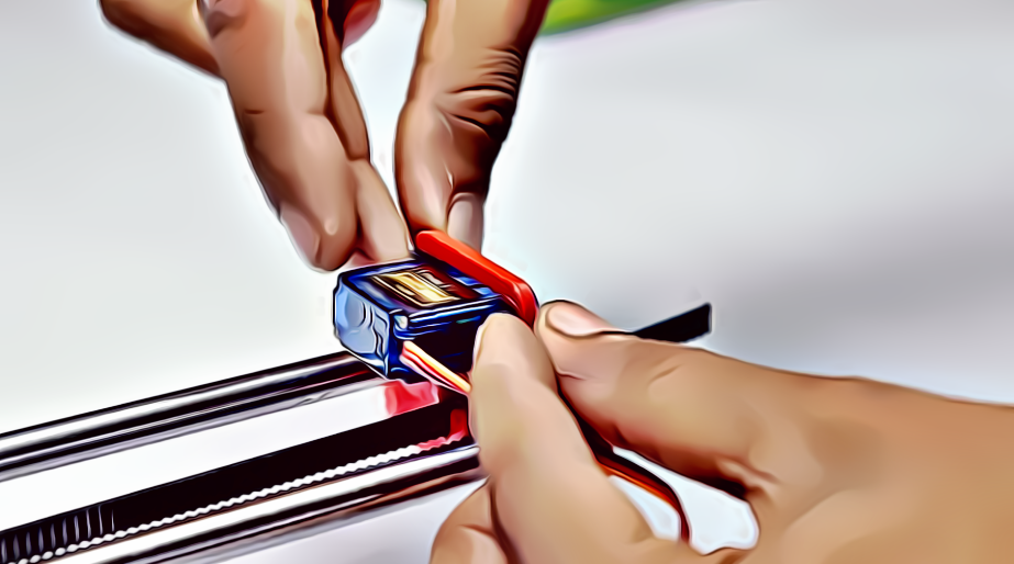
6 x Jumpers Amazon.com
1 x 12V 2A Power Supply Amazon.com
- 4 x 5/16in-18
- 13 x Phillips M3-0.5 x 16mm
- 4 x Phillips M3-0.5 x 6mm
- 5 x Phillips M4-0.7x 35mm
- 1 x Hex M3-0.5 x 20mm
- 4 x 5/16in washer
- 4 x M3 washers
Step 2: 3D Printing
PLA is fine for this design. I print at 200C on BuildTak. None of the parts require rafts or brims. I suggest supports only for the pen holder and the Z axis end plate which is standing up.
Download the files from Thingiverse
Open the 3D models in Cura or any other slicer.
Use 75% infill on all the parts (An infill of 70 – 100% will work as well)
Printed all the parts with 0.10 – 0.20 mm layer height
Printed with PLA
Use supports on the Penholder, Slider, X_Support_L and the X_Support_R
Note: The longest part took around 10hrs and the shortest took 30 minutes to print
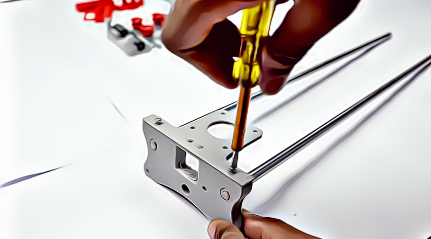
Step 3: Assemble the X-Axis
Now take the threaded rod and insert it in the hole below. Feed a 5/16in washer and 5/16in nut on both sides of the x-support part
Remember that you need (2) 350mm and (2) 450mm long linear rods
Take the (2) 450mm linear rods and insert them into either x-support part
- Use may need to use a round file to smooth out the holes that you insert them in
- Also, you can use a rubber mallet to help insert the rods
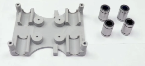
Step 4: Assemble the X-Axis Bearing
Slide the clamshell through the 450mm (X-axis) linear rods Use a rubber mallet again to attach the last X-support on the linear rods Make sure that the rods stick out equally on both sides Slide the other end of the threaded rod through the hole on the X-support Put on the last set of nuts and washers to hold the X-support in place Now that the X-axis is complete, you can use (2) Phillips M3-0.5 x 16mm screws per X-support to help keep the linear rods from sliding
Now you want to push the LM8UU bearings into their place on the top and bottom clamshell (The top and bottom clamshell take (4) bearings each)
Take (4) 624zz bearings and push them through the 3D-printed idler pulleys. Leave the 5th bearing for later when you assemble the Y-axis
Assemble the X-Axis (Carriage)
- Get (4) M3-0.5 x 20mm screws, (4) M3 nuts, (4) M3 washers and (4) 624zz bearings with the idler pulleys installed
- Take one screw and feed a washer through it, the washer will rest on the bearing. The nut will be at the bottom of the carriage, which will secure the bearing in place
Assemble the X-Axis (X-Support)
- Slide the clamshell through the 450mm (X-axis) linear rods
- Use a rubber mallet again to attach the last X-support on the linear rods
- Make sure that the rods stick out equally on both sides
- Slide the other end of the threaded rod through the hole on the X-support
- Put on the last set of nuts and washers to hold the X-support in place
- Now that the X-axis is complete, you can use (2) Phillips M3-0.5 x 16mm screws per X-support to help keep the linear rods from sliding
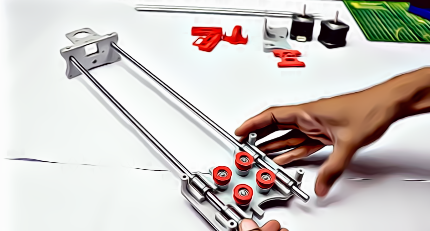
Step 5: Assemble the Y-Axis
- Slide the the linear rods/Y-back piece through the LM8UU bearings and attach the Y-front piece using a rubber mallet
- Take the (2) 350mm linear rods and insert them the Y-back piece by using a rubber mallet
- Get (1) M4-0.5 x 35 screw, (1) M4 nut and the 5th 624zz bearing
- Get (2) M3-0.5 x 16 screws to secure the linear rods
- Slide in the bearing when inserting the screw through the Y-back piece
Step 6: Assemble the X-Y Axis (Belt)
Use a pair of needle nose pliers to help guide the GT2 belt more easily through the clamshell Take the two ends of the belt and slide them through the “teeth” on the Base Slider The belt should be tight and not loose Note that once the GT2 belt is on, it is normal for the clamshell not to move easily
- Use a pair of needle nose pliers to help guide the GT2 belt more easily through the clamshell
- Take the two ends of the belt and slide them through the “teeth” on the Base Slider
- The belt should be tight and not loose
- Note that once the GT2 belt is on, it is normal for the clamshell not to move easily
Step 7: Assemble the Z-Axis
Get (2) 3mm linear rods and the following 3D printed parts (Slider, Pen Holder, Base Slide, 3MM Metric Thumb Screw) Get (1) Hex M3-0.5 x 20mm screw and the Metric Thumb Screw and push them together. Use superglue to keep it together. Get (3) M3-0.5 x 16mm screws which you will use the secure the Base Slide to the Y-Front part. You may need to use (3) M3-0.5 nuts in order to hold it in place Push the Slider and Pen Holder together to make one piece Now take that new part and the (2) 3mm linear rods and slide the rods through the holes. Place a small spring in between the two parts so there is a little bit of pressure to lift the Slider. You may need to cut the spring a bit until there is an adequate amount of pressure on the slider.
- Get (2) 3mm linear rods and the following 3D printed parts (Slider, Pen Holder, Base Slide, 3MM Metric Thumb Screw)
- Get (1) Hex M3-0.5 x 20mm screw and the Metric Thumb Screw and push them together. Use superglue to keep it together.
- Get (3) M3-0.5 x 16mm screws which you will use the secure the Base Slide to the Y-Front part. You may need to use (3) M3-0.5 nuts in order to hold it in place
- Push the Slider and Pen Holder together to make one piece
- Now take that new part and the (2) 3mm linear rods and slide the rods through the holes. Place a small spring in between the two parts so there is a little bit of pressure to lift the Slider. You may need to cut the spring a bit until there is an adequate amount of pressure on the slider.
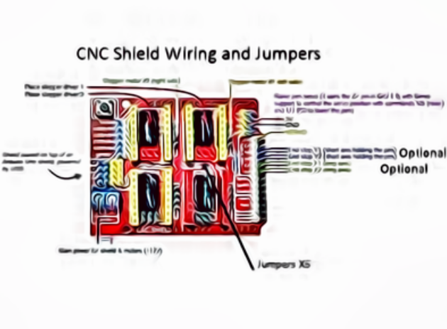
Step 8: ELECTRONICS
To find the coils of the stepper motors, use a multimeter. If there's resistance between the two wires, you have a coil. On the schematic, the coils are represented by two wires of the same color.
ELECTRONICS
i prefer you can use Arduino uno CNC Shield
Ready to your all circuit
1) 4pcs A4988 Stepper Motor Driver
2) Expansion Board A4988 Driver
3)Arduino UNO First of all take hit sink and stick on A4988 motor Driver.
4pcs A4988 Stepper motor driver connect on expansion board A4988 driver module, then connect the arduino with expansion board and connect all wiring The shield also has a built-in micro stepping control - meaning that instead of using full steps or half steps like a large CNC would do, we can make the motors move by 1/16 or 1/32 of a step to make the laser move with the maximal precision possible. However, the motors will consume more electricity: they will get hot quicker.
To use the micro stepping modes, short some of the mode pins together. Different combinations give different resolutions. Take a look at the chart for the different configurations possible. When the shield is programmed, add the A4988 drivers to it and wire up the rest of the electronics.
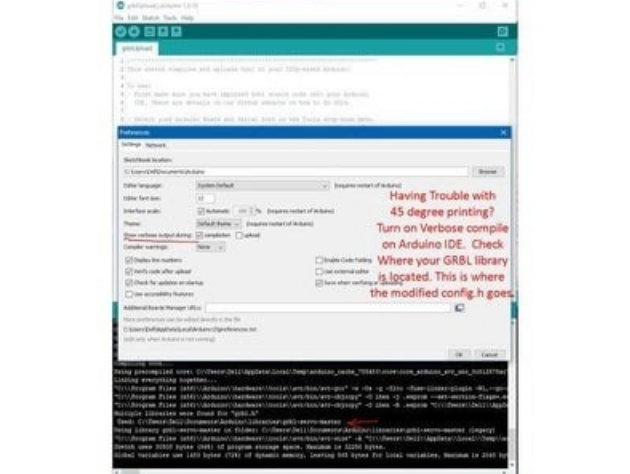
Step 9: SOFTWARE
Inkscape which is the graphics design software (draw or import graphics)
Inkscape MI GRBL Extension (convert graphics to G-Code)Universal G Code Sender (sends the G-Code to the robot causing drawing motion)GRBL which is the Arduino firmware (programmed into the Arduino Uno)
Arduino: https://www.arduino.cc/en/software
Universal G-code sender: https://winder.github.io/ugs_website/...
Inkscape: https://inkscape.org/release/inkscape..
4xiDraw & km laser: https://drive.google.com/file/d/1YO8-...
Processing: https://processing.org/download/
drawing to G-code processing: https://drive.google.com/file/d/1PIFx...
watch video for full setup
Step 10: Drawing Machine at Work
@diy.projects.lab
Related Content
- Virtual Reality
- CNC Machine
- Diyprojectslab
You May Also Like
Welcome back.
Don't have a Maker account? Create one now .
Forgot your password? Click here .
Join Our Community of Makers
Register for our site & newsletters. This gives you access to start a project, collaborate with others, and more!
This is the name that will be shown with your messages. You may use any name you wish. Once set, this cannot be changed.
Entering a password is required.
This site is protected by reCAPTCHA and the Google Privacy Policy and Terms of Service apply.
DIY Homework Writing Machine
by akashv44 in Circuits > Robots
26292 Views, 341 Favorites, 0 Comments
In this Instructable, I'll show you how to create a completely functional 3D-printed writing machine for your science fair project at school or college. This project was created as part of my second-year engineering project at Gujarat's Chandubhai S. Patel Institute of Technology (CSPIT). I also make this video for my YouTube channel "Creativity Buzz".
To design this writing instrument, I used Autodesk Fusion 360. There are many different kinds of writing robots, but in this lesson, I create a corexy writing machine. Making use of this will teach you everything there is to know about this writing robot.
All of the 3D printed parts are attached stages in the .stl file. You can download this and edit it in Autodesk Fusion 360 as necessary.
There are three types of products need to make this Writing Machine.
1) Electrical Materials
2) Hardware Materials
3) Software and Firmware
- 3D Printer https://3dflyingbear.com/
- Arduino Uno (1 pc) https://amzn.to/3GtBDFT
- CNC Shield V3 Expansion board (1 pc) https://amzn.to/3GtBDFT
- A4988 Stepper Motor Driver (2 pcs) https://amzn.to/3GtBDFT
- Nema 17 Stepper Motor ( 2 pcs) https://amzn.to/3KjIoeN
- SG90 Servo Motor (1 pc ) https://amzn.to/3ZU7arD
- 12 Volt 2 A Adapter
- 2 pin Short Jumper ( 6 pcs )
- 8 mm Threaded Rod 42 cm long and Nut (2 pcs)
- 8 mm Plain Steel Rod 35 cm long (2 pcs)
- 8 mm Plain Steel Rod 27.5 cm long (2 pcs)
- 6mm Plain Steel Rod 6.5 cm long (2 pcs)
- 7mm Spring @ 20 Rs (1 pc)
- LM8UU Slider bearing (8 pcs) https://amzn.to/3KnvtIP
- LM6UU Slider bearing (2 pcs) https://amzn.to/40TpjHk
- 623ZZ 10x4x3 mm bearing (10 pcs)
- Stepper motor Pulley GT2 (2 pcs)
- GT2 6mm Belt 2 meter https://amzn.to/3ZWBTEp
- 3mm + Nut and Bolt ( 16mm , 40 mm length )
3) Software
- Autodesk Fusion 360 ( We use this software to design 3d .stl parts to use in 3d printer to make plastic parts )https://www.autodesk.in/products/fusion-360/
- Ultimate cura ( We use this software for slice .stl file to gcode for use in 3d printer ) https://ultimaker.com/software/ultimaker-cura/
- Arduino IDE ( For Install corexy Firmware to Arduino Uno ) https://www.arduino.cc/en/software
- Inkscape version 0.92 ( For make gcode file for writing or drawing or photo to use in universal gcode sender) https://inkscape.org/release/inkscape-0.92/?latest=1
- Universal gcode sender ( Import gcode file which exported from Inkscape and give command to writing machine) https://winder.github.io/ugs_website/download/
Make Plastic Parts
We design plastic parts in Autodesk Fusion 360 and export them as .stl files. All .stl files that are attached to steps that use them. Import the stl files into the ultimaker cura slicer software and adjust the settings for the walls and nozzles you require.
Then, export the gcode file to a memory card and print it using PLA filament on a 3D printer. Make every 3D printed object step by step. To assemble this writing machine, we need 10 3D-printed components. The total weight is around 250 grammes.
Make Y Axis Slider
Take two 42 cm long 8 mm threaded rods, 8 mm nuts, and the stepper motor holder after all the 3D-printed parts have been completed printing. Then, as shown in the picture, passing this threaded road from the bottom holes in the stepper motor holder. Next, insert threaded rods from the opposite end of the second stepper motor holder.
Fix two nuts on the second end of the threaded rods after passing them through both stepper motor holders.
Added Stepper Motors
Next, take two stepper motors and insert them into the stepper motor holders' casing. Then tighten every screw on the holder joint and stepper motor.
Take two 8 mm plain steel rods that are 35 cm long and pass them through the stepper motor holder's top holes.
If you need to write on a huge scale, you can use long steel rods, although large highways reduce the quality of your writing.
Middle Slider for the X- Axis and Y-axes
After creating the y axis, create the middle slider that connects the x and y axes.
Take two middle slider plastic 3d printed parts for this, one additional 3d printed part, LM8UU Slider bearing (8 pieces), 623ZZ 10x4x3 mm bearing (8 pieces), and 40mm x 3mm bolts and nuts.
Place one 3D-printed slider object four LM8UU Slider bearings, and Attaché the other 3D-printed slider object four LM8UU Slider bearings. Next, insert four 40mm long bolts into the holes shown in the illustration. From the other side, attach two 623ZZ bearings to these bolts. Then attach all bolts from the opposite side and attach the middle 3D-printed part to the other middle part. Then secure the middle slider with the final four 40mm bolts.
After creating the middle slider, take the Y axis and remove half of the plain rod, and run the middle slider through this. After that, reattach the plain rods to the stepper motor holder.
The pen holder needs to be built once the Y-axis has been constructed.
Two 6.5 cm long 6mm plain steel rods, two LM6UU slider bearings, and a 7mm spring are the components you'll need to assemble a penholder using 3D printed materials. As shown in the picture, place two LM6UU bearings into the two holes in the grey 3D printed portion. Then, using two 6 mm plain rods, pass them through the wooden 3D-printed components of the pen holder as shown in the third picture. Place a 7 mm spring between the holder and bearing for the second rod while passing the first rod directly.
Use 16-mm bolts and nuts to attach the red pen stand to the grey 3D-printed portion.
Make X Axis
Two 27.5 cm long 8 mm plain steel rods, a pen holder, and a 3D printed belt end portion are required to make the X axis.
Attach two 8mm steel rods to the belt end 3D printed item as shown in the picture. After that, move the Y axis' middle slider over this structure. Fix the pen holder to the second end of the steel rod after that. Fix a permanent junction with two 16mm bolts.
Pulley and Roller
Then insert two 623ZZ bearings into the pen holder and fix them using a 40-mm bolt.
Get two GT2 stepper motor pulleys and attach each one individually to the stepper motor shaft.
Run GT2 Belt
Take a 2-meter GT2 belt and attach one end to the wooden belt holder portion that was 3D printed.
Next, pass the second end of the GT2 belt through the 623ZZ bearing on the middle slider, the stepper motor GT2 pulley, the 623ZZ bearing on the pen holder, the GT2 pulley, and the 623ZZ bearing on the middle slider before attaching the second end to the belt holder 3D printed component as shown in the pictures.
Make Controller Box
Arduino Uno, CNC Shield V3 Expansion board, two A4988 Stepper Motor Driver, and six short jumpers are required to create the controller box.
Take a controller box that was 3D printed and mount an Arduino Uno on it. On the Arduino Uno, attach the CNC Shield V3 Expansion board as shown in the picture. Then, as shown in the diagram, take a short jumper and place it on the CNC shield. Place the final two A4988 drivers into the CNC mill as shown in the illustration.
Servo Motor and Wiring
The final step in building a writing machine with hardware and electrical components is this.
From the back, insert the SG90 servo motor into the pen holder's cavity. After that, link the stepper motor wire to the two motors. Take the controller box and insert it through the bottom threaded rods of the Y-axis. Then connect the SG90 servo motor wire and the stepper motor wire to the controller box.
Firmware Installation
- Download the Corexy firmware using this link.
- https://github.com/jamescarruthers/PlotterXY
Download all of the software listed in this instructable's supply step.
Next, use a USB pin to connect an Arduino Uno to a computer. Next, launch the Arduino IDE software on your computer and choose the Arduino Uno board and Port.
Then use the file - open menu to open firmware in the Arduino IDE. then upload Arduino Uno with firmware.
Create a design in the Inkscape programme, then export it to the Universal Gcode Sender programme. then press "start" to begin writing on paper.
Writing on Paper
Fix the pen in the pen holder upside down, 4 mm from the paper. Then press "Start" to write on paper.
You can write or draw any image on this writing machine.
achi e vers ne v er exp o se themse l ves

- Engineering
Make a Homemade Homework Writing Machine
Drawing Robot/Pen Plotter/Drawing Machine is an Open Hardware version of the well-known AxiDraw pen plotter.
Drawing Robot/Pen Plotter/Drawing Machine is an Open Hardware version of the well-known AxiDraw pen plotter, which can write or draw on nearly any flat surface.
It can handle a wide range of applications by writing with pens, permanent markers, pencils, and other writing utensils.
Its one-of-a-kind design includes a writing head that extends outside the machine, allowing it to draw on items that are larger than the machine.
Because of the machine’s core XY extending design, it can be put over the book, which is its major benefit.
This Drawing Robot/Pen Plotter/Drawing Machine looks a lot like the AxiDraw, which is a commercially available product.
It’s controlled by an Arduino Uno, has a CNC Shield, and runs on GRBL firmware.
The cost of building the Drawing Robot varies between $75 and $150, depending on where you buy your parts and whether you already have some, such as the Arduino.
24 * 30 cm is the maximum sketching area.

Step 1: Gather the necessary parts and materials
Nema 17 stepper motors (two) 2 × M8 x 450mm Linear Rods for X Axis 2 × M8 x 350mm Linear Rods for Y Axis 2 x 3mm Linear Rods for the Z Axis (you can get it from old CDROM) 1 × Threaded Rod M8 x 480mm8 x LM8UU Bearings 1 x Sg901 x Spring 5m Servo (from ball point pen) 2 x GT2 Pulley, 16 teeth Bearing 624zz (Set of 5) 1 × 2000mm GT2 belt 1 × Arduino Uno 1 x CNC Shield 2 x A4988 stepper drivers, each with its own heatsink 6 x Jumpers 1 × 12V 2A Power Supply
M3-0.5 x M4-0.7 x M3-0.5 x M4-0.7 x M3-0.5 x M4-0.7 18 x 4 x 5/16in
Amazon\sScrews
13 × M3-0.5 x 16mm Phillips 4 pcs M3-0.5 x 6mm Phillips 5 pcs M4-0.7x 35mm Phillips 1 × M3-0.5 x 20mm Hex Washers washer, 4 x 5/16in M3 washers (four)
Step 2: 3D Printing
Thingiverse is where you can get the files.
Cura or another slicer may be used to open the 3D models.
Use a 75 percent infill on all portions (a 70 to 100 percent infill would suffice).
All pieces were printed with a layer height of 0.10–0.20 mm.
PLA was used to print this.
Use the Penholder, Slider, X Support L, and X Support R as supports.
Note: The longest component took around 10 hours to print, while the shortest took only 30 minutes.
PLA is suitable for this project.
On BuildTak, I print at 200°C.
There are no rafts or brims required for any of the sections.
Only the pen holder and the upright Z axis end plate should be supported, in my opinion.
Step 3: Put the X-Axis together
Keep in mind that you’ll need two 350mm and two 450mm linear rods.
Insert the (2) 450mm linear rods into one of the x-support parts.
You may need to smooth up the holes with a round file before inserting the rods. You may also use a rubber mallet to assist insert the rods.
The threaded rod should now be inserted into the hole below.
On both sides of the x-support section, feed a 5/16in washer and 5/16in nut.
Step 4: Put the X-Axis Bearing Together
Slide the clamshell through the 450mm linear rods (X-axis).
Attach the final X-support on the linear rods with a rubber mallet once again.
Make sure the rods are evenly spaced on both sides.
Thread the opposite end of the threaded rod through the X-hole. support’s To keep the X-support in place, add the last set of nuts and washers.
You may now add (2) Phillips M3-0.5 x 16mm screws per X-support to assist keep the linear rods from slipping now that the X-axis is complete.
Now you must push the LM8UU bearings into their proper positions on the top and bottom clamshells (each clamshell requires four bearings).
Push four 624zz bearings through the idler pulleys that were 3D-printed. When assembling the Y-axis, save the fifth bearing for later.
Construct the X-Axis (Carriage)
With the idler pulleys fitted, get (4) M3-0.5 x 20mm screws, (4) M3 nuts, (4) M3 washers, and (4) 624zz bearings.
Feed a washer through one screw; the washer will rest on the bearing.
The bearing will be secured in place by a nut at the bottom of the carriage.
You may now use (2) Phillips M3-0.5 x 16mm screws to complete the X-axis.
each X-support, screws to protect the linear rods from slipping
Step 5: Put the Y-Axis together
Using a rubber mallet, insert the (2) 350mm linear rods into the Y-back piece.
Obtain one M4-0.5 x 35 screw, one M4 nut, and the fifth 624zz bearing.
To fasten the linear rods, get two M3-0.5 x 16 screws.
When screwing the Y-back piece together, slide the bearing in.
Slide the linear rods/Y-back piece through the LM8UU bearings and use a rubber mallet to secure the Y-front piece.
Step 6: Put the X-Y Axis Together (Belt)
To make it easier to guide the GT2 belt through the clamshell, use a set of needle nose pliers.
Take the two ends of the belt and thread them through the Base Slider’s “teeth.”
The belt should be snug, not slack.
It is common for the clamshell to not move freely after the GT2 belt is installed.
Step 7: Put the Z-Axis together.
2 3mm linear rods and the 3D printed items listed below (Slider, Pen Holder, Base Slide, 3MM Metric Thumb Screw)
Take one Hex M3-0.5 x 20mm screw and one Metric Thumb Screw and combine them.
To hold things together, use superglue.
You’ll need three M3-0.5 x 16mm screws to fasten the Base Slide to the Y-Front portion.
To keep it in place, you might need to use three M3-0.5 nuts.
To make one piece, push the Slider and Pen Holder together.
Step 8: ELECTRONICS
ELECTRONICS
I recommend that you utilise the Arduino uno CNC Shield.
Prepared for your whole circuit
1) A4988 Stepper Motor Driver, 4 pcs 2) A4988 Expansion Board Driver 3)Arduino UNO (Arduino Uno)
To begin, take the hit sink and place it on the A4988 motor driver.
Attach four A4988 stepper motor drivers to the A4988 driver module on the extension board, then connect the arduino to the expansion board and connect all wire.
The shield also includes built-in micro stepping control, which means that instead of utilising full or half steps like a huge CNC, we can have the motors move by 1/16 or 1/32 of a step to move the laser with the greatest accuracy.
The motors, on the other hand, will use more electricity and become hotter more quickly.
Short several of the mode pins together to use the micro stepping modes.
Various combinations result in various resolutions.
Take a look at the diagram to see the many combinations that are available.
After the shield has been configured, connect the A4988 drivers and the rest of the electronics.
Use a multimeter to locate the stepper motor coils.
You have a coil if there is resistance between the two wires.
The coils are represented on the diagram by two wires of the same colour.
Step 9: APPLICATION SOFTWARE
Inkscape is a graphics design software programme (draw or import graphics)
MI GRBL Extension for Inkscape (convert graphics to G-Code)
G Code Sender (Universal) (sends the G-Code to the robot causing drawing motion)
The Arduino firmware is GRBL (programmed into the Arduino Uno)
Be Confident, Have Positive Gesture, Convincing Body Language, Disciplined Actions, Dedicated Approach, Be Determined, Be Transparent KP
“Update your mindset with time to improve your growth and business, Have a timely pivot” – KP
Helping Hands

About the author

pondabrothers
You can download our apps and books for free.. Search - Incognito Inventions
Ik was op zoek naar dit project van lange tijd, ik ben je echt dankbaar heel erg bedankt 🙂
Leave a Reply Cancel reply
Your email address will not be published. Required fields are marked *
- Artificial Intelligence
- Data Science
- Ethical Hacking
Homework Writing Machine with Arduino and Servo Motor
Homework writing machine is an auto writing machine through which you can make your your work easy by programing your project. As per the title this is a simple project using Arduino to make Homework writing machine at your home.This machine can draw any design and write any type of fonts.You can see sharpness and perfection of writing in photos. The machine uses a gantry to move the writing tip along the X and Y axes. The flexible-nib pen is mounted on a servo motor which rotates the tip onto the writing surface, taking care of the third axis.
Mechanical Kit will be shipped to you and you can learn and build using tutorials. You can start for free today!
1. 3D Printer
2. Automobile Prototyping
3. CNC Machine using Arduino
4. Project Management with Primavera
Homework writing machine project description:
- Servo Motor: A servomotor is a rotary actuator or linear actuator that allows for precise control of angular or linear position, velocity and acceleration.It consists of a suitable motor coupled to a sensor for position feedback. It also requires a relatively sophisticated controller, often a dedicated module designed specifically for use with servomotors. 1 threaded rod
- Wood: Wood is a porous and fibrous structural tissue found in the stems and roots of trees and other woody plants. It is an organic material, a natural composite of cellulose fibers that are strong in tension and embedded in a matrix of lignin that resists compression.
Latest projects on Mechanical
Want to develop practical skills on Mechanical? Checkout our latest projects and start learning for free
- Arduno uno: Arduino is an open source computer hardware and software company, project, and user community that designs and manufactures single-board microcontrollers and microcontroller kits for building digital devices and interactive objects that can sense and control objects in the physical and digital world. The project's products are distributed as open-source hardware and software, which are licensed under the GNU Lesser General Public License (LGPL) or the GNU General Public License (GPL),permitting the manufacture of Arduino boards and software distribution by anyone. Arduino boards are available commercially in preassembled form, or as do-it-yourself (DIY) kits.
- Grbl shield: =The Arduino grblShield is a complete hardware solution for Dank's CNC motion control system called grbl. Compatible with the Uno and other 328p versions of the Arduino development platform. (Note: grbl 0.6 is not compatible with 168-based Arduinos (nor will it ever be), and currently grbl does not support the Arduino Megas).
- Driver motors : = motor driver is a little current amplifier; the function of motor drivers is to take a low-current control signal and then turn it into a higher-current signal that can drive a motor.
- 9 gram servo : = A servomotor is a rotary actuator or linear actuator that allows for precise control of angular or linear position, velocity and acceleration.[1] It consists of a suitable motor coupled to a sensor for position feedback. It also requires a relatively sophisticated controller, often a dedicated module designed specifically for use with servomotors. Benbox software
Skyfi Labs helps students learn practical skills by building real-world projects.
You can enrol with friends and receive kits at your doorstep
You can learn from experts, build working projects, showcase skills to the world and grab the best jobs. Get started today!
- Arduino uno
- Servo Motor
- Grbl shield
- Driver motors
- Benbox software
Homework Writing Machine
Join 250,000+ students from 36+ countries & develop practical skills by building projects
Get kits shipped in 24 hours. Build using online tutorials.
More Project Ideas on Mechanical
Subscribe to receive more project ideas.
Stay up-to-date and build projects on latest technologies
☎ Have a Query?
- Online Text to STL
- 3D Printed Soldering Helper
- 3D Printed Coin Vault
- 3D Printed FLARE GUN (PROP/REPLICA) MULTI PART
- 3D Printed Mini Container with PET Bottle Cap Size
TEST 3D PRINTS
Easy & Fun Things to 3D Print

How To Make DIY Pen Plotter / Homework Writing Machine at Home
This Drawing Robot/Pen Plotter/Drawing Machine is similar to the commercially available AxiDraw. It is powered by an Arduino Uno controller, uses a CNC Shield, and GRBL firmware.
The cost to build the Drawing Robot is between $75 and $100 depending on where you buy your parts and whether you already own some of the parts such as the Arduino.
Parts and Materials Required
- 2 x Nema 17 Stepper Motors
- 2 x Linear Rod M8 x 450mm for X Axis
- 2 x Linear Rod M8 x 350mm for Y Axis
- 2 x Linear Rod 3mm for Z Axis (you can get it from old CDROM)
- 1 x Threaded Rod M8 x 480mm
- 8 x LM8UU Bearings
- 1 x Servo Sg90
- 1 x Spring 5m (from ball point pen)
- 2 x GT2 Pulley, 16 teeth
- 5 x Bearing 624zz
- 1 x 2000mm GT2 belt
- 1 x Arduino Uno
- 1 x CNC Shield
- 2 x A4988 Stepper driver with heatsink
- 6 x Jumpers
- 1 x 12V 2A Power Supply
- 4 x 5/16in-18
- 13 x Phillips M3-0.5 x 16mm
- 4 x Phillips M3-0.5 x 6mm
- 5 x Phillips M4-0.7x 35mm
- 1 x Hex M3-0.5 x 20mm
- 4 x 5/16in washer
- 4 x M3 washers
3D Printing
- Download the files from Thingiverse
- Open the 3D models in Cura or any other slicer(Sli3er, Simplify 3D, etc.)
- Use 75% infill on all the parts (An infill of 70 – 100% will work as well)
- Printed all the parts with 0.10 – 0.20 mm layer height
- Printed with Hatchbox Red PLA
- Use supports on the Penholder, Slider, X_Support_L and the X_Support_R
Note: The longest part took around 9hrs and the shortest took 30 minutes to print
3D Printed Parts

Cut your Linear Rods
Use a measuring tape and sharpie to mark the spots where the rods need to be cut
- Use a vise to hold the rods in place when you cut them
- Remember that you need (2) 350mm and (2) 450mm long linear rods
- On the threaded rod, mark your cutting point at 470mm

Assemble the X-Axis (Linear/Threaded Rods)
Take the (2) 450mm linear rods and insert them into either x-support part
- Use may need to use a round file to smooth out the holes that you insert them in
- Also, you can use a rubber mallet to help insert the rods
Now take the threaded rod and insert it in the hole below. Feed a 5/16in washer and 5/16in nut on both sides of the x-support part

Assemble the X-Axis (Bearings)
Now you want to push the LM8UU bearings into their place on the top and bottom clamshell (The top and bottom clamshell take (4) bearings each)
Take (4) 624zz bearings and push them through the 3D-printed idler pulleys. Leave the 5th bearing for later when you assemble the Y-axis

Assemble the X-Axis (Carriage)
- Get (4) M3-0.5 x 20mm screws, (4) M3 nuts, (4) M3 washers and (4) 624zz bearings with the idler pulleys installed
- Take one screw and feed a washer through it, the washer will rest on the bearing. The nut will be at the bottom of the carriage, which will secure the bearing in place

Assemble the X-Axis (X-Support)
- Slide the clamshell through the 450mm (X-axis) linear rods
- Use a rubber mallet again to attach the last X-support on the linear rods
- Make sure that the rods stick out equally on both sides
- Slide the other end of the threaded rod through the hole on the X-support
- Put on the last set of nuts and washers to hold the X-support in place
- Now that the X-axis is complete, you can use (2) Phillips M3-0.5 x 16mm screws per X-support to help keep the linear rods from sliding

Assemble the X-Axis (Stepper Motors)
- Use an appropriate sized allen wrench to attach the 16 teeth pulleys on the stepper motor shafts
- Flipping the entire chassis around will make it easier to attach the stepper motors
- Use (8) M3-0.5 x 6mm screws and a Phillips screwdriver to attach the (2) stepper motors
Assemble the Y-Axis (Clamshell)
(Optional if you have problems keeping belt on bearings)
- Grab (4) M4-0.5 x 35mm screws and (4) M4 nuts
- Make sure that you have the (4) idler pulleys ( Download from Thingiversa ) and the (4) washers printed
- Insert the washers in between the two clamshells, with a screw in between
- Screw the top and bottom clamshells together

Assemble the Y-Axis (Y- Back/Front)
- Take the (2) 350mm linear rods and insert them the Y-back piece by using a rubber mallet
- Get (1) M4-0.5 x 35 screw, (1) M4 nut and the 5th 624zz bearing
- Get (2) M3-0.5 x 16 screws to secure the linear rods
- Slide in the bearing when inserting the screw through the Y-back piece
- Slide the the linear rods/Y-back piece through the LM8UU bearings and attach the Y-front piece using a rubber mallet

Assemble the X-Y Axis (Belt)
- Use a pair of needle nose pliers to help guide the GT2 belt more easily through the clamshell
- Take the two ends of the belt and slide them through the “teeth” on the Base Slider
- The belt should be tight and not loose
- Note that once the GT2 belt is on, it is normal for the clamshell not to move easily
Belt Diagram

Assemble the Z-Axis
- Get (2) 3mm linear rods and the following 3D printed parts (Slider, Pen Holder, Base Slide, 3MM Metric Thumb Screw)
- Get (1) Hex M3-0.5 x 20mm screw and the Metric Thumb Screw and push them together. Use superglue to keep it together.
- Get (3) M3-0.5 x 16mm screws which you will use the secure the Base Slide to the Y-Front part. You may need to use (3) M3-0.5 nuts in order to hold it in place
- Push the Slider and Pen Holder together to make one piece
- Now take that new part and the (2) 3mm linear rods and slide the rods through the holes. Place a small spring in between the two parts so there is a little bit of pressure to lift the Slider. You may need to cut the spring a bit until there is an adequate amount of pressure on the slider.

Step By Step Video
The Original Instructions by Henry Arnold Jonathan K
- 3D Printed Hairy Lion →
12 thoughts on “ How To Make DIY Pen Plotter / Homework Writing Machine at Home ”
i constructed all the machine but when i press X+ the both X and Y axis are moving what is the problem
double check the steppers wiring
Have you solved it? I have the same problem with my machine, when I press X+, it’s necessary both motors move at same time, but, only one of them move…
Did you solve this problem?
Same problem how to solve ,?
Is it true that you didn’t use the microswitches in the final design?
Hello how to co figurę this machine to RUN on GRBL. What I mean is that GRBL interprets commands for x axis and y axis independently and if I look on your belt diagram it looks like both Motors have to run at the same time in order to move the carriage along y axis… How did you do that?
Have you solved it?
Thank you, thank you. It’s a very good built.
Is it possible to modify it to draw using brush ang oil based paint ?
Could you please tell what software/plug in and which version do you use to generate g-code for this machine?
Hello, what is the width of your belt? 6mm or 10mm? Thanks!
Leave a Reply Cancel reply
Your email address will not be published. Required fields are marked *
Save my name, email, and website in this browser for the next time I comment.
Embed the widget on your own site

Drawing Robot/Pen Plotter/Drawing Machine is an Open Hardware version of the famous machine AxiDraw which it is a pen plotter, capable of wr
Make DIY Homework Writing Machine at Home
Step 1: parts and materials required, step 2: 3d printing, step 3: assemble the x-axis, step 4: assemble the x-axis bearing, step 5: assemble the y-axis.
- Step 6: Assemble the X-Y Axis (Belt
Step 7: Assemble the Z-Axis
Step 8: electronics, step 9: software, step 10: drawing machine at work.
- Comments (8)

Things used in this project

 Software apps and online services Hand tools and fabrication machines
Drawing Robot/Pen Plotter/Drawing Machine is an Open Hardware version of the famous machine AxiDraw which it is a pen plotter, capable of writing or drawing on almost any flat surface. It can write with pens, permanent markers, pencils, and other writing implements to handle an endless variety of applications. Its unique design features a writing head that extends beyond the machine, making it possible to draw on objects bigger than the machine itself. The biggest advantage of the machine is that it can be placed over the book because of the core XY extending design of the machine. This Drawing Robot/Pen Plotter/Drawing Machine is similar to the commercially available AxiDraw. It is powered by an Arduino Uno controller, uses a CNC Shield, and GRBL firmware The cost to build the Drawing Robot is between $75 depending on where you buy your parts and whether you already own some of the parts such as the Arduino. You can find all of my projects on https://www.diyprojectslab.com/ Maximum drawing area 24 * 30 CM. Thank You NextPCB This project is successfully completed because of the help and support from NextPCB. Guys if you have a PCB project, please visit their website and get exciting discounts and coupons. Free shipping 0$ PCB Prototype: https://www.nextpcb.com/pcb-quote?act=2&code=Romeo... Thanksgiving Christmas lucky draw 100% win: https://www.nextpcb.com/christmas-lucky-draw?code... 2 x Nema 17 Stepper Motors Amazon.com 2 x Linear Rod M8 x 450mm for X Axis Amazon.com 2 x Linear Rod M8 x 350mm for Y Axis Amazon.com 2 x Linear Rod 3mm for Z Axis (you can get it from old CDROM) 1 x Threaded Rod M8 x 480mm8 x LM8UU Bearings Amazon.com 1 x Servo Sg901 x Spring 5m (from ball point pen) Amazon.com 2 x GT2 Pulley, 16 teeth Amazon.com 5 x Bearing 624zz Amazon.com 1 x 2000mm GT2 belt Amazon.com 1 x Arduino Uno Amazon.com 1 x CNC Shield Amazon.com 2 x A4988 Stepper driver with heatsink Amazon.com 6 x Jumpers Amazon.com 1 x 12V 2A Power Supply Amazon.com
Download the files from Thingiverse Open the 3D models in Cura or any other slicer. Use 75% infill on all the parts (An infill of 70 – 100% will work as well) Printed all the parts with 0.10 – 0.20 mm layer height Printed with PLA Use supports on the Penholder, Slider, X_Support_L and the X_Support_R Note: The longest part took around 10hrs and the shortest took 30 minutes to print PLA is fine for this design. I print at 200C on BuildTak. None of the parts require rafts or brims. I suggest supports only for the pen holder and the Z axis end plate which is standing up. Remember that you need (2) 350mm and (2) 450mm long linear rods Take the (2) 450mm linear rods and insert them into either x-support part
Now take the threaded rod and insert it in the hole below. Feed a 5/16in washer and 5/16in nut on both sides of the x-support part Now you want to push the LM8UU bearings into their place on the top and bottom clamshell (The top and bottom clamshell take (4) bearings each) Take (4) 624zz bearings and push them through the 3D-printed idler pulleys. Leave the 5th bearing for later when you assemble the Y-axis Assemble the X-Axis (Carriage)
Assemble the X-Axis (X-Support)
Step 6: Assemble the X-Y Axis (Belt)
ELECTRONICS I prefer you can use Arduino uno CNC Shield Ready to your all circuit 1) 4pcs A4988 Stepper Motor Driver 2) Expansion Board A4988 Driver 3)Arduino UNO First of all take hit sink and stick on A4988 motor Driver. 4pcs A4988 Stepper motor driver connect on expansion board A4988 driver module, then connect the arduino with expansion board and connect all wiring The shield also has a built-in micro stepping control - meaning that instead of using full steps or half steps like a large CNC would do, we can make the motors move by 1/16 or 1/32 of a step to make the laser move with the maximal precision possible. However, the motors will consume more electricity: they will get hot quicker. To use the micro stepping modes, short some of the mode pins together. Different combinations give different resolutions. Take a look at the chart for the different configurations possible. When the shield is programmed, add the A4988 drivers to it and wire up the rest of the electronics. To find the coils of the stepper motors, use a multimeter. If there's resistance between the two wires, you have a coil. On the schematic, the coils are represented by two wires of the same color. Inkscape which is the graphics design software (draw or import graphics) Inkscape MI GRBL Extension (convert graphics to G-Code)Universal G Code Sender (sends the G-Code to the robot causing drawing motion)GRBL which is the Arduino firmware (programmed into the Arduino Uno) Arduino: https://www.arduino.cc/en/software Universal G-code sender: https://winder.github.io/ugs_website/... Inkscape: https://inkscape.org/release/inkscape.. 4xiDraw & km laser: https://drive.google.com/file/d/1YO8-... Processing: https://processing.org/download/ drawing to G-code processing: https://drive.google.com/file/d/1PIFx... watch video for full setup hookup_QLVR1z3Ob1.jpg DIY Projects LabRelated channels and tags. 
Consider these available items
Sorry, there was a problem.Image unavailable. 
 AxiDraw V3 Personal Writing & Drawing RobotReturn policy. Tap on the category links below for the associated return window and exceptions (if any) for returns. 10 Days ReturnableYou can return if you receive a damaged, defective or incorrect product. 10 Days, RefundReturnable if you’ve received the product in a condition that is damaged, defective or different from its description on the product detail page on Amazon.in. Refunds will be issued only if it is determined that the item was not damaged while in your possession, or is not different from what was shipped to you. Movies, MusicNot returnable, musical instruments. Wind instruments and items marked as non-returnable on detail page are not eligible for return. Video Games (Accessories and Games)You can ask for a replacement or refund if you receive a damaged, defective or incorrect product. Mobiles (new and certified refurbished)10 days replacement, mobile accessories. This item is eligible for free replacement/refund, within 10 days of delivery, in an unlikely event of damaged, defective or different/wrong item delivered to you. Note: Please keep the item in its original condition, with MRP tags attached, user manual, warranty cards, and original accessories in manufacturer packaging. We may contact you to ascertain the damage or defect in the product prior to issuing refund/replacement. Power Banks: 10 Days; Replacement only Screen guards, screen protectors and tempered glasses are non-returnable. Used Mobiles, Tablets10 days refund. Refunds applicable only if it has been determined that the item was not damaged while in your possession, or is not different from what was shipped to you. Mobiles and Tablets with Inspect & Buy label2 days refund, tablets (new and certified refurbished), 7 days replacement. This item is eligible for free replacement, within 7 days of delivery, in an unlikely event of damaged or different item delivered to you. In case of defective, product quality related issues for brands listed below, customer will be required to approach the brands’ customer service center and seek resolution. If the product is confirmed as defective by the brand then customer needs to get letter/email confirming the same and submit to Amazon customer service to seek replacement. Replacement for defective products, products with quality issues cannot be provided if the brand has not confirmed the same through a letter/email. Brands -HP, Lenovo, AMD, Intel, Seagate, Crucial Please keep the item in its original condition, with brand outer box, MRP tags attached, user manual, warranty cards, CDs and original accessories in manufacturer packaging for a successful return pick-up. Before returning a Tablet, the device should be formatted and screen lock should be disabled. For few products, we may schedule a technician visit to your location. On the basis of the technician's evaluation report, we will provide resolution. This item is eligible for free replacement, within 7 days of delivery, in an unlikely event of damaged, defective or different item delivered to you. Please keep the item in its original condition, with brand outer box, MRP tags attached, user manual, warranty cards, CDs and original accessories in manufacturer packaging for a successful return pick-up. Used LaptopsSoftware products that are labeled as not returnable on the product detail pages are not eligible for returns. For software-related technical issues or installation issues in items belonging to the Software category, please contact the brand directly. Desktops, Monitors, Pen drives, Hard drives, Memory cards, Computer accessories, Graphic cards, CPU, Power supplies, Motherboards, Cooling devices, TV cards & Computing ComponentsAll PC components, listed as Components under "Computers & Accessories" that are labeled as not returnable on the product detail page are not eligible for returns. Digital Cameras, camera lenses, Headsets, Speakers, Projectors, Home Entertainment (new and certified refurbished)Return the camera in the original condition with brand box and all the accessories Product like camera bag etc. to avoid pickup cancellation. We will not process a replacement if the pickup is cancelled owing to missing/damaged contents. Return the speakers in the original condition in brand box to avoid pickup cancellation. We will not process a replacement if the pickup is cancelled owing to missing/ damaged box. 10 Days, ReplacementSpeakers (new and certified refurbished), home entertainment. This item is eligible for free replacement, within 10 days of delivery, in an unlikely event of damaged, defective or different/wrong item delivered to you. Note: Please keep the item in its original condition, with MRP tags attached, user manual, warranty cards, and original accessories in manufacturer packaging for a successful return pick-up. For TV, we may schedule a technician visit to your location and resolution will be provided based on the technician's evaluation report. 10 days Replacement onlyThis item is eligible for free replacement, within 10 days of delivery, in an unlikely event of damaged, defective or different/wrong item delivered to you. . Please keep the item in its original condition, original packaging, with user manual, warranty cards, and original accessories in manufacturer packaging for a successful return pick-up. If you report an issue with your Furniture,we may schedule a technician visit to your location. On the basis of the technician's evaluation report, we will provide resolution. Large Appliances - Air Coolers, Air Conditioner, Refrigerator, Washing Machine, Dishwasher, MicrowaveIn certain cases, if you report an issue with your Air Conditioner, Refrigerator, Washing Machine or Microwave, we may schedule a technician visit to your location. On the basis of the technician's evaluation report, we'll provide a resolution. Home and KitchenGrocery and gourmet, pet food, pet shampoos and conditioners, pest control and pet grooming aids, non-returnable, pet habitats and supplies, apparel and leashes, training and behavior aids, toys, aquarium supplies such as pumps, filters and lights, 7 days returnable. All the toys item other than Vehicle and Outdoor Category are eligible for free replacement/refund, within 7 days of delivery, in an unlikely event of damaged, defective or different/wrong item delivered to you. Vehicle and Outdoor category toys are eligible for free replacement, within 7 days of delivery, in an unlikely event of damaged, defective or different/wrong item delivered to you Note: Please keep the item in its original condition, with outer box or case, user manual, warranty cards, and other accompaniments in manufacturer packaging for a successful return pick-up. We may contact you to ascertain the damage or defect in the product prior to issuing refund/replacement. Sports, Fitness and OutdoorsOccupational health & safety products, personal care appliances, 7 days replacement only, health and personal care, clothing and accessories, 30 days returnable. Lingerie, innerwear and apparel labeled as non-returnable on their product detail pages can't be returned. Return the clothing in the original condition with the MRP and brand tag attached to the clothing to avoid pickup cancellation. We will not process a replacement or refund if the pickup is cancelled owing to missing MRP tag. Precious JewelleryPrecious jewellery items need to be returned in the tamper free packaging that is provided in the delivery parcel. Returns in any other packaging will not be accepted. Fashion or Imitation Jewellery, Eyewear and WatchesReturn the watch in the original condition in brand box to avoid pickup cancellation. We will not process a replacement if the pickup is cancelled owing to missing/damaged contents. Gold Coins / Gold Vedhanis / Gold Chips / Gold Bars30 days; replacement/refund, 30 days, returnable, luggage and handbags. Any luggage items with locks must be returned unlocked. Car Parts and Accessories, Bike Parts and Accessories, Helmets and other Protective Gear, Vehicle ElectronicsItems marked as non-returnable on detail page are not eligible for return. Items that you no longer need must be returned in new and unopened condition with all the original packing, tags, inbox literature, warranty/ guarantee card, freebies and accessories including keys, straps and locks intact. Fasteners, Food service equipment and supplies, Industrial Electrical, Lab and Scientific Products, Material Handling Products, Occupational Health and Safety Products, Packaging and Shipping Supplies, Professional Medical Supplies, Tapes, Adhesives and Sealants Test, Measure and Inspect items, Industrial Hardware, Industrial Power and Hand Tools.Tyres (except car tyres), rims and oversized items (automobiles). Car tyres are non-returnable and hence, not eligible for return. Return pickup facility is not available for these items. You can self return these products using any courier/ postal service of your choice. Learn more about shipping cost refunds . The return timelines for seller-fulfilled items sold on Amazon.in are equivalent to the return timelines mentioned above for items fulfilled by Amazon. If you’ve received a seller-fulfilled product in a condition that is damaged, defective or different from its description on the product detail page on Amazon.in, returns are subject to the seller's approval of the return. If you do not receive a response from the seller for your return request within two business days, you can submit an A-to-Z Guarantee claim. Learn more about returning seller fulfilled items. Note : For seller fulfilled items from Books, Movies & TV Shows categories, the sellers need to be informed of the damage/ defect within 14 days of delivery. For seller-fulfilled items from Fine Art category, the sellers need to be informed of the damage / defect within 10 days of delivery. These items are not eligible for self-return. The seller will arrange the return pick up for these items. For seller-fulfilled items from Sports collectibles and Entertainment collectibles categories, the sellers need to be informed of the damage / defect within 10 days of delivery. The General Return Policy is applicable for all Amazon Global Store Products (“Product”). If the Product is eligible for a refund on return, you can choose to return the Product either through courier Pickup or Self-Return** Note: - Once the package is received at Amazon Export Sales LLC fulfillment center in the US, it takes 2 (two) business days for the refund to be processed and 2- 4 business days for the refund amount to reflect in your account. - If your return is due to an Amazon error you'll receive a full refund, else the shipping charges (onward & return) along with import fees will be deducted from your refund amount. **For products worth more than INR 25000, we only offer Self-Return option. 2 Days, Refund Refunds are applicable only if determined that the item was not damaged while in your possession, or is not different from what was shipped to you.
Brand in this category on Amazon Product informationTechnical details.
Additional Information
Looking for specific info?Product description. introducing the AxiDraw V3 The AxiDraw is a simple, modern, precise, and versatile pen plotter, capable of writing or drawing on almost any flat surface. It can write with your favorite fountain pens, permanent markers, and other writing implements to handle an endless variety of applications. Its unique design features a writing head that extends beyond the machine, making it possible to draw on objects bigger than the machine itself. Applications: The AxiDraw is an extremely versatile machine, designed to serve a wide variety of everyday and specialized drawing and writing needs. You can use it for almost any task that might normally be carried out with a handheld pen. It allows you to use your computer to produce writing that appears to be handmade, complete with the unmistakable appearance of using a real pen (as opposed to an inkjet or laser printer) to address an envelope or sign one's name. And it does so with precision approaching that of a skilled artist, and — just as importantly — using an arm that never gets tired. Customer reviews
No customer reviews
DIY CNC Writing Machine Using GRBL Introduction: DIY CNC Writing Machine Using GRBL In this project, I will show you how to easily build your own low-cost Arduino CNC Plotter Using Free and Open-Source Software! I’ve come across a lot of tutorials explaining how to build your own CNC plotter, but not a single one that explains in detail about all the details and software required to make it happen. I had to cross-refer with a hell lot of tutorials to make this project happen. Everything including the details of the software used are mentioned in this tutorial. Thus, I wanted to share this with the society for anyone who wishes to create this Project. Step 1: WHAT YOU’LL NEED
Step 2: BASIC OVERVIEWThe heart of this machine is the Arduino working with the CNC Shield and the Stepper Motors. The stepper motors are used to actuate the X and Y axes. Two gantries each consisting of one stepper motor is made and constructed using acrylic. Each axis is controlled separately by the Arduino running the GRBL Firmware which is free and open-source. The pen attached on the Z-Axis is controlled using a servo. Step 3: MAKING THE FRAME Download the given Illustrator file and use your respective Mill/LaserCutter/3D Printer to make the pieces for the frame. Also cut out the supports for the Stepper motor. AttachmentsStep 4: creating the adapter for the motor.  I 3D modeled the adapter for the model in Fusion 360 according to the dimensions of my rod and motor shaft. The stl and fusion files are linked down below. It can also be found on my TinkerCAD profile. Download the files and 3D print the Adapter. Click here for the TinkerCAD file.  Step 5: ASSEMBLING THE GANTRIES
Step 6: MOUNTING THE GANTRIES ON TOP OF EACH OTHER Slide-in nuts on both the threaded rods and the plain rods and fix them in place. Glue a piece of acrylic spaning over both the rods. Glue the Y axis gantry to this piece of acrylic, Step 7: MAKING THE PEN HOLDER CNC out the required parts and put them together to form the mechanism shown in the images. Attach the Servo in the given spot using glue. Step 8: WIRING THE MACHINE Connect the male jumpers in between the Driver holders to enable micro-stepping. connect the rest of the parts as mentioned in the wiring diagram. Power the parts using a 12v supply Step 9: REFER THE VIDEO BY CREATTIVE BUZZ FOR CLEARER DETAILS ON THE MECHANICAL CONSTRUCTIONI've done my Mechanical construction all in reference to this video, all credits to the owner. Step 10: SOFTWAREStep 11: flashing grbl to the arduino. The main Software running on the Arduino that controls the Motors is GRBL. TO flash it :
Step 12: INKSCAPE FOR SENDING THE GCODE Download Inkscape Version 0.47 from here . and install it. Step 13: DOWNLOADING AND ADDING THE GRBL EXTENTION TO INKSCAPEDownload the below-given files Refer to this video for details on how to install the extension in Inkscape. Step 14: UNIVERSAL G CODE SENDERDownload the Universal G Code sender and unzip it. FROM HERE . Step 15: CALIBRATING THE STEPS PER MM FOR G CODE SENDER Open the G-Code Sender aplication.
Step 16: Creating the GCODE FILE
SIT BACK AND LET THE MACHINE DRAW. 
No products in the cart. Return to shop  EasyDraw V2 Writing and Drawing Machine kit (NOT ASSEMBLED) ₹ 7,990.00 (inc GST)
DRAWINGBOT is an Open Hardware version of the famous machine AxiDraw which it is a pen plotter, capable of writing or drawing on almost any flat surface. It can write with pens, permanent markers, pencils, and other writing implements to handle an endless variety of applications. Its unique design features a writing head that extends beyond the machine, making it possible to draw on objects bigger than the machine itself. The biggest advantage of the machine is that it can be placed over the book because of the core XY extending design of the machine. Maximum drawing area 24 * 30 CM. All parts are 3d printed in ABS plastic in 70 °C heated chamber which makes the 3d printed layer very strong. PLA parts are bad its brittle and break easily and lose strength after few months and the glass transition temperature of PLA is very low so if will place the parts under the sun or inside a parked car under the sun. the parts will slowly melt and deform and become unusable. All of the above problems are solved by using ABS plastic. ABS is tricky to print its printed in a special water-cooled actively heated chamber 3dprinter. The electronics parts Arduino, stepper motor drivers, and custom CNC shield is assembled and tested by us, so you dont have to upload any code or solder anything. An inexperienced person can easily assemble it. All parts are included in the kit, only a screwdriver and a laptop or PC is needed from your side. WARRANTY: 2D PLOTTER kit (NOT ASSEMBLED) has no warranty only the 2D CNC PLOTTER (FULLY ASSEMBLED) has 3 months warranty. if any of the parts get damaged during shipping you can contact us via WhatsApp / PH: 8590094244 we will send you replacement parts. ASSEMBLING VIDEOSOFTWARE VIDEO
14 reviews for EasyDraw V2 Writing and Drawing Machine kit (NOT ASSEMBLED)
 Aibel K – 06/05/2022 good quality parts  Ishan Taniwal – 29/06/2022  Janaki GanGa Rao – 04/08/2022  Ajay Sharma – 02/09/2022  Aval Satani – 19/10/2022 Good working machine 🙂👍  Balakrishnan R – 09/11/2022 Super very excellent and existing this  chandrakala k. – 16/12/2022  Aniket – 18/03/2023 Nice product  Vaibhav – 29/03/2023 Amazing and superb stuff as well as customer service is also appreciable .Well done Q maker.#Time saving stuff#Nice😊  Siwas Rajbanshi – 21/04/2023  gaurav biswas – 30/05/2023 Excellent product 😉  Aarya Malik – 12/12/2023  Aman Shaikh – 24/01/2024 The software part is bit unsatisfactory  Armaan – 01/06/2024 Only logged in customers who have purchased this product may leave a review. Related products EasyDraw V2 2D Plotter 3d printed parts (ABS plastic) kit  EasyDraw V2 EasyDraw V2 Writing and Drawing Machine (FULLY ASSEMBLED) Username or email address * Password * Remember me Log in Lost your password? Email address * Your personal data will be used to support your experience throughout this website, to manage access to your account, and for other purposes described in our privacy policy . | ||||||||||||||||||||||||||||||||||||||||||||||||||||||||||
IMAGES
VIDEO
COMMENTS
DIY Homework Writing Machine: In this Instructable, I'll show you how to create a completely functional 3D-printed writing machine for your science fair project at school or college. ... Take two middle slider plastic 3d printed parts for this, one additional 3d printed part, LM8UU Slider bearing (8 pieces), 623ZZ 10x4x3 mm bearing (8 pieces ...
Step 3: Assemble the X-Axis. Now take the threaded rod and insert it in the hole below. Feed a 5/16in washer and 5/16in nut on both sides of the x-support part. Remember that you need (2) 350mm and (2) 450mm long linear rods. Take the (2) 450mm linear rods and insert them into either x-support part.
Step 1: Assembly - Y Axis. Take the 2040mm profile and attach the base plates to both the ends. Use the sliding nuts and m4 bolts to attach the base plates to the profiles. Now turn the profile and attach rubber feet to the bottom slots of the base plates. These rubber feet will hold the machine in place on smooth surfaces.
Take the (2) 350mm linear rods and insert them the Y-back piece by using a rubber mallet. Get (1) M4-0.5 x 35 screw, (1) M4 nut and the 5th 624zz bearing. Get (2) M3-0.5 x 16 screws to secure the linear rods. Slide in the bearing when inserting the screw through the Y-back piece.
In this video we make homework writing machine using Arduino uno and stepper motors.This writing machine can be used for writing and drawing in science proje...
This is the Version 2.0 of the Arduino Homework Writing Machine - 2D CNC Plotter. this version comes with a lot of upgrades from the previous one, which incl...
You may need to use (3) M3-0.5 nuts in order to hold it in place. Push the Slider and Pen Holder together to make one piece. Now take that new part and the (2) 3mm linear rods and slide the rods through the holes. Place a small spring in between the two parts so there is a little bit of pressure to lift the Slider.
DIY Homework Writing Machine. by akashv44 in Circuits > Robots. 26076 Views, 341 Favorites, 0 Comments DIY Homework Writing Machine ... Take two middle slider plastic 3d printed parts for this, one additional 3d printed part, LM8UU Slider bearing (8 pieces), 623ZZ 10x4x3 mm bearing (8 pieces), and 40mm x 3mm bolts and nuts. ...
Make a Homemade Homework Writing Machine. April 6, 2022. by pondabrothers. 7 min read. 1 Comment. ... The cost of building the Drawing Robot varies between $75 and $150, depending on where you buy your parts and whether you already have some, such as the Arduino. 24 * 30 cm is the maximum sketching area. Step 1: Gather the necessary parts and ...
Homework writing machine project description: Servo Motor: A servomotor is a rotary actuator or linear actuator that allows for precise control of angular or linear position, velocity and acceleration.It consists of a suitable motor coupled to a sensor for position feedback. It also requires a relatively sophisticated controller, often a dedicated module designed specifically for use with ...
Get (2) 3mm linear rods and the following 3D printed parts (Slider, Pen Holder, Base Slide, 3MM Metric Thumb Screw) Get (1) Hex M3-0.5 x 20mm screw and the Metric Thumb Screw and push them together. Use superglue to keep it together. Get (3) M3-0.5 x 16mm screws which you will use the secure the Base Slide to the Y-Front part.
Step 4: Unscrew Stepper Motor. Open one screw on sliding shaft and 2 screw on stepper motor. Disassemble stepper motor and sliding parts from one rectangle. Remove all circuit of sliding part and cut middle part of this sliding part. Now you have 2 PCs of plastic part.Combine both plastic object and stick with FeviQuik.
How to Make Homework Writing Machine at homeLearn How to make homework writing and drawing machine at home using Stepper motor.You can make this type of auto...
Installation. 1. Download and run the AxiDraw software installer for Windows: Download link (21 MB ZIP archive) The installer is an executable, named "AxiDraw_391.exe"; Unzip, open, and run it. 2. Download and install Inkscape version 1.2 from the download page at Inkscape.org. (Most users will want the 64-bit version and the "MSI ...
Take the (2) 350mm linear rods and insert them the Y-back piece by using a rubber mallet. Get (1) M4-0.5 x 35 screw, (1) M4 nut and the 5th 624zz bearing. Get (2) M3-0.5 x 16 screws to secure the linear rods. Slide in the bearing when inserting the screw through the Y-back piece. Y-Front.
Step 2: Building X and Y Axis Carriages. Take out the stepper Motor from dvd writer as in the picture. You need to open 2 dvd writers carefully without damaging anything inside it. Screw one carriage which contained the stepper motor to the 1ft.x1ft. board, this is the X-axis motor carriage. Keep some gap for Y axis motor carriage to be placed .
DRAWINGBOT is an Open Hardware version of the famous machine AxiDraw which it is a pen plotter, capable of writing or drawing on almost any flat surface. It can write with pens, permanent markers, pencils, and other writing implements to handle an endless variety of applications. Its unique design features a writing head that extends beyond the ...
PRECISE COMPUTER CONTROLLED HANDWRITING MACHINE - The Axidraw V3 XY Plotter Allows You to Perform a Variety of Tasks with Virtually Any Pen or Marker on Any Writing Surface. EXTREMELY VERSATILE MACHINE, Designed to Serve a Wide Variety of Everyday and Specialized Drawing and Writing Needs. You Can Use it For Almost Any Task That Might Normally ...
Easydraw v3 purchase link :https://shopmakerq.com/product/easydraw-v3-writing-and-drawing-machine-fully-assembled/Hello, friends this time I have amazing CNC...
Step 16: Creating the GCODE FILE. Open Inkscape. Import the desired image and convert it to path. In Extensions, Use the MI GRBL EXTENSION. Press apply and create the GCODE FILE. Open File mode in GCODE Sender. choose the file. hit send. SIT BACK AND LET THE MACHINE DRAW.
EasyDraw V2 Writing and Drawing Machine kit (NOT ASSEMBLED) Rated 4.50 out of 5 based on 14 customer ratings. (14 customer reviews) ₹ 7,990.00 (inc GST) In stock. EasyDraw V2 Writing and Drawing Machine kit (NOT ASSEMBLED) quantity. Add to cart. Add to wishlist. SKU: 14 Category: EasyDraw V2.
How to Make Homework Machine at homeLearn How to make homework writing and drawing machine at home using Stepper motor.You can make this type of automatic wr...
Buy now: https://shopmakerq.com/product/easydraw-v3-writing-and-drawing-machine-fully-assembled/This is a CNC pen plotter which can write and draw with pen ...