- Cisco ISE (Identity Services Engine)
- ENCOR (350-401)
- ENWLSD (300-425)
- Overview of Wireless Site Surveys
- Performing Walk-through Surveys
- Performing Layer 1 Site Surveys
- Overview of Predictive Site Surveys
- RRM Overview
- Transmit Power Control
- (RX-SOP) Receive Start of Packet
- Neighbour Discovery Protocol
- RF Profiles
- Out of Box RF Profile
- Powering APs
- Cisco Wireless Licensing
- Wireless Roaming Concepts
- Validate Mobility Messaging
- AP Redundancy
- Controller Failure Detection
- AP Fallback
- AP Prioritization

Transmit Power Control (TPC)
One of the functions that makes up the RRM operations is Transmit Power Control (TPC) . In this lesson, we’ll be taking a closer look at the TPC algorithm and how it works.
2.0 Wired and Wireless Infrastructure 2.3 Design radio management
APs can broadcast and operate using a number of different power levels. The higher the power is set on our APs, the bigger our coverage cell. Due to this, the transmit power configured on APs needs to be managed to reduce co-channel interference. Can you imagine having to manage the power on each AP manually? Even then, having to find the right transmit power for your environment? It would be a nightmare… Thankfully, TPC (Transmit Power Control) can manage this for us automatically.
TPC is an algorithm that runs on our wireless controller every 10 minutes by default. The main aim is to set an APs transmit power to its optimal value. This value will provide the best performance to clients whilst avoiding interference with other APs. As the AP will most likely have an antenna on the 2.4GHz and 5Ghz bands, TPC will run independently. There will be one transmit power set for the 2.4GHz radio and another for the 5GHz radio.
As the wireless controller has no idea how our wireless network is setup, NDP (Neighbour Discovery Protocol) is used to build the topology. Using the NDP frames, our WLC will The WLC looks for APs that can hear each other at -70dBm or greater . In addition for this, in order for the TPC algorithm to operate, the AP must be able to hear an additional 3 APs.
We might have scenarios where we have a number of wireless controllers within our deployment. If this is the case, the controller allocated as RF group leader will run the TPC algorithm.
Now that you understand how TPC operates, let’s take a look at how the algorithm works. Our wireless controller will use the following criteria to determine if a TPC change is required:
1. Can the AP detect three other APs at -70dBm? 2. Use the following formula to determine the transmit power: Tx_Max + (Tx Power Control threshold – RSSI of 3rd highest neighbour)
In order to minimise potential disruption, RRM will only make gradual changes to the transmit power. As such, RRM will only increase or decrease the power by 3dB (half or double the transmit power).
Configuration
In most cases, TPC doesn’t require any configuration to work. There might however be situations where the TPC algorithm needs to be tweaked.
TPC configuration can applied using either of the following options:
- RF Profiles.
It’s worth noting that some TPC parameters can only be configured globally. This includes;
- TPC Version.
- How TPC runs.
Global Configuration:
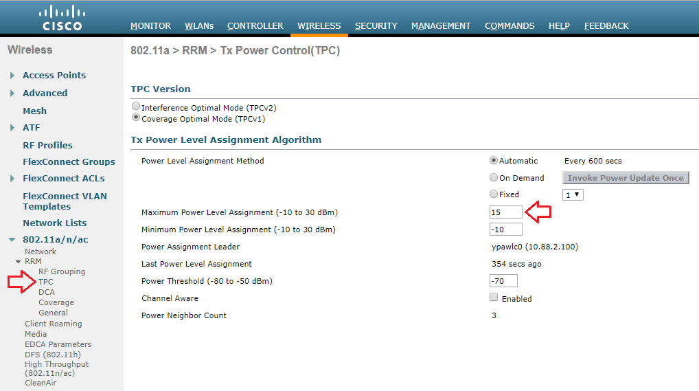
Remember that the TPC algorithm runs independently on each 802.11 band. As such, we have a global TPC configuration for the 2.4GHz band (802.11b/g/n/ax) and one for the 5GHz band (802.11a/n/ac/ax) . The 2.4GHz global configuration can be configured by navigating to: WIRELESS > 802.11b/g/n/ax > RRM > TPC The 5GHz global configuration on the other hand can be configured by navigating to: WIRELESS > 802.11a/n/ac/ax > RRM > TPC
There are a number of configurable options available to TPC global configuration. This includes:
- TPC run method.
- Maximum power level assignment.
- Minimum power level assignment.
- Power threshold.
TPC Version:
There are two methods of TPC available:
- TPCv1 (Coverage Optimal Mode).
- TPCv2 (Interference Optimal Mode).
Unless you have a specific reason otherwise, it’s recommended to use the default TPCv1 – Coverage Optimal Mode .
TPC Run Method:
TPC can run using one of the following methods:
Minimum / Maximum Power Level Assignment:
These thresholds can be used to set the minimum or maximum amount of power that APs can use within the environment.
Power Threshold:
Finally, this is the cutoff used by RRM to determine whether it should reduce an APs power. An increase of the power threshold will cause the AP to operate at higher transmit power rates. A decrease of the threshold on the other hand will cause the AP to operate at lower transmit power rates.
RF Profile:
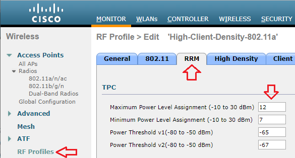
Alternately, we can control TPC parameters using RF profiles. Our RF profile can then be applied to AP groups to control TPC on specific APs. In our example, I’ve created an RF profile called MN_RF-Profile-2.4GHz .
The TPC parameters can be configured under the RRM tab of our RF profile. We can then amend the following configuration parameters:
- Maximum Power Level Assignment.
- Minimum Power Level Assignment.
- Power Threshold v1.
- Power Threshold v2.
Wait, but Wi-Fi?
Transmit Power Control Considerations
Proper configuration of Transmit Power Control (TPC) settings can help to ensure that your Access Point (AP) does not speak too loudly. If your AP is transmitting at 18dBm and an associated client station (STA) is at the cell edge and only capable of transmitting at 15dBm, your client will be able to hear the AP transmission, but the AP won’t be able to hear the client which leads to retransmissions and thus reduced performance.
Wireless network design is ultimately dependent upon the clients it is to support, so we will want to have an idea of what our intended clients are capable of. As an example, one of my customer’s clients is an HP EliteBook 8470p laptop workstation which has a Broadcom BCM943228HM4L Wi-Fi adapter. According to the product specification web page for this particular model, I was able to find that it is capable of transmitting at around 15dBm. If this is my customer’s least capable device, I would not want my AP to transmit louder than 15dBm either.
My customer is using a Cisco 3504 Wireless Controller running AireOS version 8.8. I am able to globally configure the Maximum Power Level Assignment to 15dBm.
If the same controller were managing multiple locations with different requirements, I can also set a Maximum Power Level Assignment for different RF Profiles.
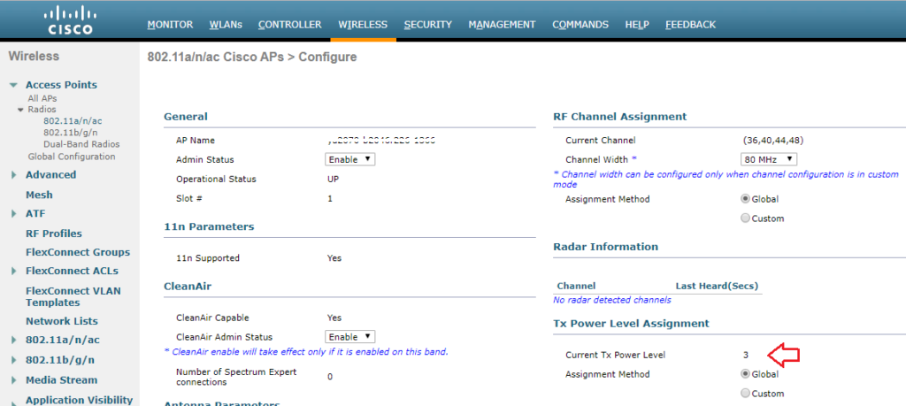
Though the maximum power level is configured in dBm, Cisco uses a series of numbers to represent levels of power. Phil Morgan of NC-Expert wrote an article titled WLC and AP Power settings in which he discusses Cisco power levels in further detail. In his article, he discusses how we can determine what the power levels represent as they vary by AP model, band (2.4 vs 5GHz), and even channel groupings (i.e. U-NII 1, 2, 2e, 3).
I also stumbled upon an excellent post by Maxim Risman in the Cisco Community titled Cisco Access point 2802i Tx Power Chart where he demonstrates the use of another very helpful command which summarizes the power levels of all APs: show advanced 802.11a txpower
Note that the range for the power levels actually does not change, but rather TPC is limiting the highest level that can be used.
The current power level setting can also be found in the web GUI by navigating to Wireless > Access Points > Radios. There, you can see the power level for all of your APs in a column, or you can dive in to the configuration of a radio.
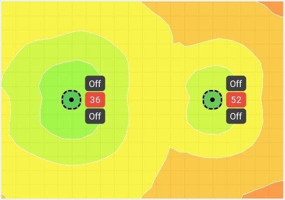
When performing predictive site surveys with Ekahau Pro site survey software, we have the ability to adjust the transmit power with which to generate our expected heat maps.
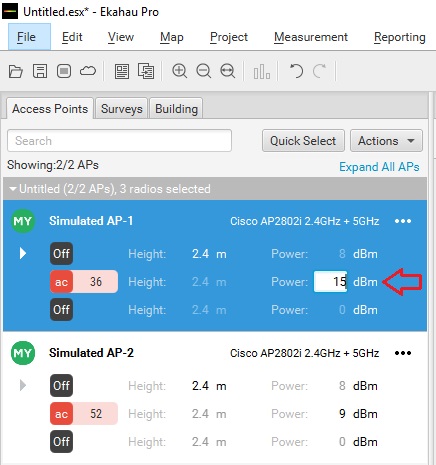
We can get an idea of how this difference may affect our design in the real world.
If you are interested in getting deeper into Cisco’s TPC implementation, you may want to check out a whitepaper they have published titled Transmit Power Control (TPC) Algorithm .

Published by Stephen
View all posts by Stephen
- Skip to content
- Skip to search
- Skip to footer
Cisco Wireless Controller Best Practices
Bias-free language.
The documentation set for this product strives to use bias-free language. For the purposes of this documentation set, bias-free is defined as language that does not imply discrimination based on age, disability, gender, racial identity, ethnic identity, sexual orientation, socioeconomic status, and intersectionality. Exceptions may be present in the documentation due to language that is hardcoded in the user interfaces of the product software, language used based on RFP documentation, or language that is used by a referenced third-party product. Learn more about how Cisco is using Inclusive Language.
- Infrastructure
RF Management

Chapter: RF Management
Client band select, 40-mhz channel width, auto dynamic channel assignment, auto transmit power control, auto coverage hole detection, event driven radio resource management.
Description— Number of WLANs should be less than 4.
We recommend limiting the number of service set identifiers (SSIDs) configured at the controller. You can configure 16 simultaneous SSIDs (per radio on each AP), but as each WLAN/SSID needs separate probe responses and beaconing, the RF pollution increases as more SSIDs are added. Furthermore, some smaller wireless stations like PDA, WiFi Phones, and barcode scanners cannot cope with a high number of basic SSID (BSSID) information. This results in lockups, reloads, or association failures. Also the more SSIDs, the more beaconing needed, so less RF time is available for real data transmits. For example, the recommendation is to have one to three SSIDs for corporate, and one SSID for high-density designs. AAA override can be leveraged for per user VLAN/ settings on a single SSID scenario.
Selected—Less than or equal to 4
Unselected—Greater than 4
Verify the number of WLANs by entering this command:
(Cisco Controller) > show wlan summary
Disable unwanted WLANs by entering this command:
(Cisco Controller) > config wlan disable wlan-id
Description—Band Selection should be enabled. Clicking Fix it Now enables Band Selection.
Band selection is enabled/disabled globally by default.
Band selection works by regulating probe responses to clients. It makes 5 GHz channels more attractive to clients by delaying probe responses to clients on 2.4 GHz channels.
Evaluate band selection for voice, particularly focusing on roaming performance. See below for further explanation.
Most newer model clients prefer 5 GHz by default if the 5 GHz signal of the AP is equal to or stronger than the 2.4-GHz signal.
Band select should be enabled for high-density designs
Also, in high-density designs, the study of available UNII-2 channels should be made. Those channels that are unaffected by Radar and also usable by the client base should be added to the RRM DCA list as usable channels.
Dual-band roaming can be slow depending on the client. If a majority of the base of voice clients exhibits a slow roaming behavior, it is more likely that the client sticks to 2.4 GHz. In this case, it has scanning issues on 5 GHz. Generally when a client decides to roam, it scans its current channel and band first. The clients generally scan for an AP that has a significantly better signal level, maybe as much as 20 dB and/or a significantly better SNR. Failing such available connection, the client may remain with its current AP. In this case, if the CU on 2.4 GHz is low and the call quality is not poor, then disabling the selected band maybe fine. However, the preferred design is to enable band selection on 5 GHz with all data rates enabled and 6 Mbps as mandatory. Then, set the 5 GHz RRM minimum Tx power level 6 dBm higher than the average 2.4 GHz power level set by RRM.
The goal of this configuration recommendation is to enable the client to obtain a band and channel with better SNR and Tx power initially. As already stated, generally when a client decides to roam, it scans its current channel and band first. So, if the client initially joins the 5 GHz band, then it is more likely to stay on the band if there are good power levels on 5 GHz. SNR levels on 5 GHz are generally better than 2.4 GHz because 2.4 GHz has only three Wi-Fi channels and is more susceptible to interference such as Bluetooth, iBeacons, and microwave signals.
802.11k is recommended to be enabled with dual-band reporting. This enables all 11k enabled clients to have the benefit of assisted roaming. With dual-band reporting enabled, the client receives a list of the best 2.4-GHz and 5-GHz APs upon a directed request from the client. Here, the client most likely looks at the top of the list for an AP on the same channel, and then on the same band as the client is currently on. This logic reduces scan times and saves battery power. Having 802.11k enabled on the WLC does not have a downside effect for non-802.11k clients.
Selected—Enabled on all WLANs
Unselected—Disabled
Verify Band Select by entering this command:
(Cisco Controller) > show band-select
Enable Band Select on a WLAN by entering this command:
(Cisco Controller) > config wlan band-select allow enable wlan-id
Description—Channel width should be set to 40 MHz. Clicking Fix it Now sets the channel width to 40 MHz.
Selected—Enabled
Description—Auto DCA should be enabled to allow RRM to select best channels for each radio. Clicking Fix it Now enables Auto DCA.
When a wireless network is first initialized, all radios participating require a channel assignment to operate without interference - optimizing the channel assignments to allow for interference free operation is DCA's job. Wireless network does this using the air metrics reported by each radio on every possible channel, and providing a solution that maximizes channel bandwidth and minimizes RF interference from all sources - Self (signal), other networks (foreign interference), Noise (everything else).
DCA is enabled by default and provides a global solution to channel planning for your network.
Selected—DCA is enabled for 802.11a/b
Unselected—None or one is enabled
CLI Option—Enable auto DCA by entering this command:
(Cisco Controller) > config 802.11a channel global auto
(Cisco Controller) > config 802.11b channel global auto
Description—Auto TPC should be enabled to allow RRM to select best transmit power for each radio. Clicking Fix it Now enables Auto TPC.
The Cisco WLC dynamically controls the access point transmit power based on real-time wireless LAN conditions. You can choose between two versions of transmit power control: TPCv1 and TPCv2. With TPCv1, power can be kept low to gain extra capacity and reduce interference. With TPCv2, transmit power is dynamically adjusted with the goal of minimum interference. TPCv2 is suitable for dense networks. In this mode, there could be higher roaming delays and coverage hole incidents.
Selected—TPC enabled for 802.11a/b
Unselected—None or one enabled
CLI Option—Enable Auto TPC by entering this command:
(Cisco Controller) > config 802.11a txPower global auto
(Cisco Controller) > config 802.11b txPower global auto
Description—Auto CHD should be enabled.
The controller uses the quality of client signal levels reported by the APs to determine if the power level of that AP needs to be increased. Coverage Hole Detection (CHD) is controller independent, so the RF group leader is not involved in those calculations. The controller knows how many clients are associated with a particular AP and what are the signal-to-noise ratio (SNR) values for each client.
If a client SNR drops below the configured threshold value on the controller, the AP increases its power level to try to compensate for the client. The SNR threshold is based on the transmit power of the AP and the coverage profile settings on the controller.
For instructions on how to configure auto CHD, see the Cisco Wireless LAN Controller Configuration Guide .
Selected—CHD enabled
Unselected— None or one enabled
Description—CleanAir should be enabled. Clicking Fix it Now enables CleanAir.
To effectively detect and mitigate RF interference, enable CleanAir whenever possible. There are recommendations to various sources of interference to trigger security alerts, such as generic DECT phones, jammer, and so on.
Verify CleanAir configuration on a network by entering this command:
(Cisco Controller) > show 802.11{a|b} cleanair config
Enable CleanAir functionality on a network by entering this command:
(Cisco Controller) > config 802.11{a|b} cleanair enable network
Configure to enable interference detection for specifically jammer by entering this command:
(Cisco Controller) > config 802.11{a|b} cleanair device enable jammer
Description—Event driven RRM should be enabled. Clicking Fix it Now enables event driven RRM.
Was this Document Helpful?

Contact Cisco
- (Requires a Cisco Service Contract )
Unlimited Access
Exam 350-401 topic 1 question 407 discussion.
If the maximum power level assignment for global TPC 802.11a/n/ac is configured to 10 dBm. which power level effectively doubles the transmit power?
siteoforigin
Rafaelinho88, get it certification.
Unlock free, top-quality video courses on ExamTopics with a simple registration. Elevate your learning journey with our expertly curated content. Register now to access a diverse range of educational resources designed for your success. Start learning today with ExamTopics!
Log in to ExamTopics
Report comment.
verbs.studio
Coming soon.
IMAGES
VIDEO
COMMENTS
TPC Min and Max settings are entered in dBm NOT Power level index. For this you will want to know the allowed powers for the AP model you are configuring. Power level index is a scale 1-8 from (1)Max to (8) Minimum power for the AP.
The maximum and minimum TPC power settings apply to all the access points through RF profiles in a RF network. To set the Maximum Power Level Assignment and Minimum Power Level Assignment, enter the maximum and minimum transmit power used by RRM in the fields in the Tx Power Control window. The range for these parameters is -10 to 30 dBm.
TPC adjusts the Tx power up or down to meet the required coverage level indicated by the TPC Threshold. In order to configure RRM to do the TPC calculations, you need to set the txPower assignment to global with the command config { 802.11a | 802.11b } txPower global auto .
The maximum and minimum TPC power settings apply to all the access points through RF profiles in a RF network. To set the Maximum Power Level Assignment and Minimum Power Level Assignment, enter the maximum and minimum transmit power used by RRM in the fields in the Tx Power Control window. The range for these parameters is -10 to 30 dBm.
TPC page also shows few non-configurable parameter settings. 1 Power Neighbor Count : The minimum number of neighbors an AP must have for TPC algorithm to run. 2.Power Assignment Leader: The IP Address of RF group leader, who is responsible for power level assignment. 3.Last Power Level Assignmnet: The last time RRM evaluated current TPC ...
However, power level 1 is always the maximum power level allowed per country code setting, with each successive power level representing 50% of the previous power level. For example, 1 = maximum power level in a particular regulatory domain, 2 = 50% power, 3 = 25% power, 4 = 12.5% power, and so on.
The TPC parameters can be configured under the RRM tab of our RF profile. We can then amend the following configuration parameters: Maximum Power Level Assignment. Minimum Power Level Assignment. Power Threshold v1. Power Threshold v2. One of the functions that makes up the RRM operations is Transmit Power Control (TPC).
Though the maximum power level is configured in dBm, Cisco uses a series of numbers to represent levels of power. Phil Morgan of NC-Expert wrote an article titled WLC and AP Power settings in which he discusses Cisco power levels in further detail. In his article, he discusses how we can determine what the power levels represent as they vary by AP model, band (2.4 vs 5GHz), and even channel ...
Maximum and minimum settings for transmit power are available. The defaults are 30dBm for maximum power and -10dBm for minimum power. The power threshold is the minimum level at which you need to hear the third AP for the TPC algorithm to run. The default is -70dBm. You can set it higher or lower depending on your needs.
After the TPC algorithm has run and adjusted an AP's power level, that level is remembered the next time the AP is power cycled. DCA Recall from Chapter 7, "Planning Coverage with Wireless APs," and Chapter 12, "Understanding Roaming," that a proper channel assignment is vital for efficient use of air time and for client mobility.
(Cisco Controller) > config 802.11b channel global auto. Auto Transmit Power Control. Description—Auto TPC should be enabled to allow RRM to select best transmit power for each radio. Clicking Fix it Now enables Auto TPC. The Cisco WLC dynamically controls the access point transmit power based on real-time wireless LAN conditions.
If the maximum power level assignment for global Transmit Power Control (TPC) for 802.11a/n/ac is configured to 10 dBm, then doubling the transmit power would require an increase of 3 dBm. A 3 dBm increase represents a doubling of the power level, so a power level of 13 dBm would effectively double the transmit power.
It can be configured to match inner identity (currently mac-address only) which allows to focus on traffic related to specific client event when CAPWAP encapsulated. monitor capture client_inner_mac inner mac f0c1.f10b.8ac1 interface vlan39 both control-plane both. monitor capture client_inner_mac match any.
The Tx Power Level Assignment for each AP shows its current power level assignment in a numbering system that starts with 1 the ends with 8. The number 1 indicates the APO exists off full power and the higher the number goes less strength are transmitted. ... DCA Customize TPC. UNII-2Ext. Receiving Service Num Of Supported Energy Levels ...
The maximum and minimum TPC power settings apply to all access points through RF profiles in a RF network. To set the Maximum Power Level Assignment and Minimum Power Level Assignment, enter the maximum and minimum transmit power used by RRM in the text boxes in the Tx Power Control page. The range for these parameters is -10 to 30 dBm....