Developing a Work Breakdown Structure
- First Online: 30 April 2020

Cite this chapter

- Gus Cicala 2
1653 Accesses
3 Altmetric
At the end of the chapter, the reader should be able to
This is a preview of subscription content, log in via an institution to check access.
Access this chapter
Subscribe and save.
- Get 10 units per month
- Download Article/Chapter or eBook
- 1 Unit = 1 Article or 1 Chapter
- Cancel anytime
- Available as PDF
- Read on any device
- Instant download
- Own it forever
- Available as EPUB and PDF
- Compact, lightweight edition
- Dispatched in 3 to 5 business days
- Free shipping worldwide - see info
Tax calculation will be finalised at checkout
Purchases are for personal use only
Institutional subscriptions
Author information
Authors and affiliations.
Wilmington, DE, USA
You can also search for this author in PubMed Google Scholar
Rights and permissions
Reprints and permissions
Copyright information
© 2020 Augustus Cicala Jr
About this chapter
Cicala, G. (2020). Developing a Work Breakdown Structure. In: The Project Managers Guide to Microsoft Project 2019 . Apress, Berkeley, CA. https://doi.org/10.1007/978-1-4842-5635-0_6
Download citation
DOI : https://doi.org/10.1007/978-1-4842-5635-0_6
Published : 30 April 2020
Publisher Name : Apress, Berkeley, CA
Print ISBN : 978-1-4842-5637-4
Online ISBN : 978-1-4842-5635-0
eBook Packages : Professional and Applied Computing Apress Access Books Professional and Applied Computing (R0)
Share this chapter
Anyone you share the following link with will be able to read this content:
Sorry, a shareable link is not currently available for this article.
Provided by the Springer Nature SharedIt content-sharing initiative
- Publish with us
Policies and ethics
- Find a journal
- Track your research
Information
- Author Services
Initiatives
You are accessing a machine-readable page. In order to be human-readable, please install an RSS reader.
All articles published by MDPI are made immediately available worldwide under an open access license. No special permission is required to reuse all or part of the article published by MDPI, including figures and tables. For articles published under an open access Creative Common CC BY license, any part of the article may be reused without permission provided that the original article is clearly cited. For more information, please refer to https://www.mdpi.com/openaccess .
Feature papers represent the most advanced research with significant potential for high impact in the field. A Feature Paper should be a substantial original Article that involves several techniques or approaches, provides an outlook for future research directions and describes possible research applications.
Feature papers are submitted upon individual invitation or recommendation by the scientific editors and must receive positive feedback from the reviewers.
Editor’s Choice articles are based on recommendations by the scientific editors of MDPI journals from around the world. Editors select a small number of articles recently published in the journal that they believe will be particularly interesting to readers, or important in the respective research area. The aim is to provide a snapshot of some of the most exciting work published in the various research areas of the journal.
Original Submission Date Received: .
- Active Journals
- Find a Journal
- Proceedings Series
- For Authors
- For Reviewers
- For Editors
- For Librarians
- For Publishers
- For Societies
- For Conference Organizers
- Open Access Policy
- Institutional Open Access Program
- Special Issues Guidelines
- Editorial Process
- Research and Publication Ethics
- Article Processing Charges
- Testimonials
- Preprints.org
- SciProfiles
- Encyclopedia

Article Menu
- Subscribe SciFeed
- Recommended Articles
- Google Scholar
- on Google Scholar
- Table of Contents
Find support for a specific problem in the support section of our website.
Please let us know what you think of our products and services.
Visit our dedicated information section to learn more about MDPI.
JSmol Viewer
Integration of cost and work breakdown structures in the management of construction projects.

1. Introduction
2. literature review, 2.1. work breakdown structure (wbs), 2.1.1. wbs in the international pm standards, 2.1.2. wbs in the construction industry.
- The decomposition criteria, grouping activities into construction units assigned to the different contractors, and/or subcontractors involved in the execution of the project.
- The degree of work complexity and level of detail that identifies the sequence and other relations between the activities in a logical flow of execution.
- The criticality of the tasks, being defined in terms of units of work, according to their importance to avoid activity preemption.
- Organizational unit’s fixed responsibility.
- Clear deliverable.
- Exact scope of work.
- Reliable schedule estimation.
- Specific risk resolution.
- Reliable cost estimation.
- Specific organizational guideline.
2.2.1. Costs Based on Activities
2.2.2. coding systems in the construction industry.
- Consistency (single classification principle).
- Mutual exclusivity of categories.
- Exhaustiveness.
- Identify the final result (or deliverable) to achieve the objectives.
- Review the scope to ensure consistency between requirements and the WBS elements.
- Define the chapters (first level of decomposition) in a way that facilitates the understanding by dividing them into clearly differentiated blocks.
- Continue to break down each chapter to an appropriate level of detail.
- Break down the chapters to the final level of detail (construction unit), where both the cost and the schedule are reliable, allowing efficient project monitoring and control.
- Review and refine the WBS until main stakeholders agree on the planning and execution.
2.3. Integration of WBS and CBS
2.4. bim in the construction industry, 3. methodology.
- CSCAE (Higher Council of the Colleges of Architects of Spain).
- CGATE (Spanish General Council of Technical Architecture).
- CCIP (College of Civil Engineering, Channels and Ports of Spain).
- CITOP (College of Technical Engineers in Public Works of Spain).
- CGCOII (Higher Council of Colleges of Industrial Engineers of Spain).
- COGITI (Spanish General Council of Technical Industrial Engineering).
- AEIPRO (Spanish Project Management and Engineering Association).
- PMA (Project Managers Association of Andalusia).
- PMI (Chapters of Andalusia, Balearic Islands, Barcelona, Madrid and Valencia).
- AECMA (Spanish Association of Construction Management).
- AEGC (Spanish Construction Management Association).
- B&M (Building and Management).
- AEPDP (Spanish Association of Project Management Practitioners).
- CCPM (Construction Certified Project Managers PMP).
- CMAS (Construction Management Association of Spain).
- DIP (Integrated Project Management).
- DP (Building and Infrastructure Project Managers and Professionals).
- IAC (Engineering, Architecture and Construction).
- ISO 21500 (Project Management).
- Search&Drive (Architecture and Engineering Professionals).
- TL (Architecture, Construction and Engineering Technicians).
- The age and experience in the construction industry of both groups is quite similar.
- Technician practitioners (CIT sample) mostly work in smaller companies, whereas construction managers (CIM sample), while still work more for small companies, also work in companies with other sizes.
- The project duration and cost size tends to be higher in the projects where construction managers participate.
- The knowledge and training of PM methodologies (e.g., ISO 21500, PMI PMBOK, IPMA ICB, etc.) is almost null in the case of technicians, and fairly high in the case of construction managers.
- PM certification is much more common among construction managers too (probably an expected outcome).
4.1. Hypotheses
4.2. confirmatory factor analysis (cfa), 4.2.1. principal components.
- (F1) Scope design (which involves the project managers and key stakeholders agreeing on the requirements, defining the scope and deliverables characteristics, specifications and acceptance criteria).
- (F2) Scope development (which involves the project managers and their management team, breaking down the work to be done, avoiding tasks omission, and identifying the project activities).
- (C1) Project success (which includes the constraints performance, the stakeholders’ satisfaction, and the outcomes usability).
- (C2) Organization success (which includes the strategic objectives compliance, market positioning, and the business profit generation).
4.2.2. Validity
- The total variance explained by the principal components, was greater than 50%.
- The measure of sampling adequacy, by the Kaiser–Meyer–Olkin test [ 149 , 150 ], was greater than to 0.5.
- The model applicability, by the Bartlett’s sphericity test [ 151 ], discarded a lack of correlation between items, as it presented a high Chi-square and a significance lower than 5%.
4.3. Structural Equation Model (SEM)
- Define a model explaining a complete set of (significant) relationships.
- Uncover unobserved (indirect) relationships between variables.
- Estimate multiple and interrelated dependence relationships.
- Consider measurement errors in the estimations.
- Test the model where a structure can be imposed and assessed as to fit of the data.
- Reliability: By the Cronbach’s alpha and composite reliability.
- Validity: By the standardized regression weights and squared multiple correlations, as well as the average extracted variance.
- Goodness of fit: By absolute, incremental, and parsimonious fit measures.
4.3.1. Reliability
- Cα > 0.9 as excellent.
- 0.9 > Cα > 0.8 as good.
- 0.8 > Cα > 0.7 as acceptable.
- 0.7 > Cα > 0.6 as questionable.
- 0.6 > Cα > 0.5 as poor.
- 0.5 > Cα as unacceptable.
4.3.2. Validity
4.3.3. goodness of fit.
- Absolute fit measures (AFMs).
- Incremental fit measures (IFMs).
- Parsimonious fit measures (PFMs).
4.3.4. Indirect Effects
4.3.5. direct effects, 5. discussion, 6. conclusions.
- The WBS involves structuring the project scope in a hierarchical manner. It is oriented to the deliverables, and avoids both duplication and omission of tasks.
- As the project work is defined more clearly, project roles and responsibilities can be assigned to subcontractors and organizational units more easily. This, in turn, also allows to define more representative project schedules and budgets.
Author Contributions
Conflicts of interest.
- PwC. When Will You Think Differently about Programme Delivery ; PwC: London, UK, 2014. [ Google Scholar ]
- Project Management Institute. The High Cost of Low Performance. How Will You Improve Business Results ; Project Management Institute: Newtown Square, PA, USA, 2016. [ Google Scholar ]
- Fortune, J.; White, D.; Jugdev, K.; Walker, D. Looking again at current practice in project management. Int. J. Manag. Proj. Bus. 2011 , 4 , 553–572. [ Google Scholar ] [ CrossRef ] [ Green Version ]
- Davis, K. Different stakeholder groups and their perceptions of project success. Int. J. Proj. Manag. 2014 , 32 , 189–201. [ Google Scholar ] [ CrossRef ]
- KPMG International. Climbing the Curve ; KPMG International: Amstelveen, The Netherlands, 2015. [ Google Scholar ]
- Demirkesen, S.; Ozorhon, B. Measuring Project Management Performance: Case of Construction Industry. Eng. Manag. J. 2017 , 29 , 258–277. [ Google Scholar ] [ CrossRef ]
- Heywood, C.; Smith, J. Integrating stakeholders during community FM’s early project phases. Facilities 2006 , 24 , 300–313. [ Google Scholar ] [ CrossRef ]
- International Project Management Association. Individual Competence Baseline for Project, Programme & Portfolio Management , 4th ed.; IPMA: Zurich, Switzerland, 2015; ISBN 978-9492338013. [ Google Scholar ]
- Project Management Institute. A Guide to the Project Management Body of Knowledge. PMBOK Guide , 6th ed.; PMI: Newtown Square, PA, USA, 2017; ISBN 978-1628253825. [ Google Scholar ]
- Wang, Y. Applying the PDRI in Project Risk Management ; The University of Texas at Austin: Austin, TX, USA, 2002. [ Google Scholar ]
- Anticona, P. Does BIM offer a better approach to guarantee a reliable, accurate, and precise Cost Estimate? PM World J. 2019 , VIII , 1–28. [ Google Scholar ]
- Camilleri, E. Project Success: Critical Factors and Behaviours , 1st ed.; Gower Publishing: Burlington, VT, USA, 2011; ISBN 978-0566092282. [ Google Scholar ]
- García-Fornieles, J.M.; Fan, I.S.; Perez, A.; Wainwright, C.; Sehdev, K. A Work Breakdown Structure that Integrates Different Views in Aircraft Modification Projects. Concurr. Eng. 2003 , 11 , 47–54. [ Google Scholar ] [ CrossRef ] [ Green Version ]
- Kim, S.; Park, C.; Lee, S.; Son, J. Integrated cost and schedule control in the Korean construction industry based on a modified work-packaging model. Can. J. Civ. Eng. 2008 , 35 , 225–235. [ Google Scholar ] [ CrossRef ]
- Cerezo-Narváez, A.; Otero-Mateo, M.; Pastor-Fernández, A. Influence of scope management in construction industry projects. DYNA Manag. 2016 , 4 , 1–15. [ Google Scholar ]
- Ibrahim, Y.M.; Kaka, A.P.; Trucco, E.; Kagioglou, M.; Ghassan, A. Semi-automatic development of the work breakdown structure (WBS) for construction projects. In Proceedings of the 4th International Salford Centre for Research and Innovation (SCRI) Research Symposium, Salford, UK, 26–27 March 2007; Salford Centre for Research and Innovation (SCRI): Salford, UK, 2007; pp. 133–145. [ Google Scholar ]
- Ballesteros-Pérez, P.; Cerezo-Narváez, A.; Otero-Mateo, M.; Pastor-Fernández, A.; Zhang, J.; Vanhoucke, M. Forecasting the Project Duration Average and Standard Deviation from Deterministic Schedule Information. Appl. Sci. 2020 , 10 , 654. [ Google Scholar ] [ CrossRef ] [ Green Version ]
- Fageha, M.K.; Aibinu, A.A. Prioritising Project Scope Definition Elements in Public Building Projects. Australas. J. Constr. Econ. Build. 2014 , 14 , 18–33. [ Google Scholar ] [ CrossRef ] [ Green Version ]
- Chritamara, S.; Ogunlana, S.O.; Bach, N.L. Investigating the effect of initial scope establishment on the performance of a project through system dynamics modelling. Eng. Constr. Archit. Manag. 2001 , 8 , 381–392. [ Google Scholar ] [ CrossRef ]
- Gómez-Senent Martínez, E. El Proyecto. Diseño en Ingeniería ; Servicio de Publicaciones de la Universidad Politécnica de Valencia UPV: Valencia, Spain, 1997; ISBN 978-8477214540. [ Google Scholar ]
- Wang, Y.-R.; Gibson, G.E., Jr. A study of preproject planning and project success using ANN and regression models. In Proceedings of the 25th International Symposium on Automation and Robotics in Construction, Vilnius, Lithuania, 26–29 June 2008; Vilnius Gediminas Technical University: Vilnius, Lithuania, 2008; pp. 688–696. [ Google Scholar ]
- Thaweejinda, J.; Methakullawat, N. Guideline for Clearly Definition Scope ; Chulalongkorn University: Bangkok, Thailand, 2012. [ Google Scholar ]
- Kraus, W. Analysis and Cost Estimating. Cost Eng. J. 2008 , 50 , 3–4. [ Google Scholar ]
- Seidel Calazans, A.T.; Dias Kosloski, R.A. O gerenciamento da alteração de escopo na contratação externa de serviços de desenvolvimento/manutenção de software. In Proceedings of the 13th Argentine Symposium on Software Engineering (ASSE), La Plata, Argentina, 27–31 August 2012; Sociedad Argentina de Informática: La Plata, Argentina, 2012; pp. 75–90. [ Google Scholar ]
- Khan, A. Project Scope Management. Cost Eng. J. 2006 , 48 , 12–16. [ Google Scholar ]
- Stal-Le Cardinal, J.; Marle, F. Project: The just necessary structure to reach your goals. Int. J. Proj. Manag. 2006 , 24 , 226–233. [ Google Scholar ] [ CrossRef ]
- Sikdar, S.; Das, O. Goal based project scope determination approach. In Proceedings of the IEEE International Conference of Science and Technology for Humanity (TIC-STH), Toronto, ON, Canada, 26–27 September 2009; IEEE: Toronto, ON, Canada, 2009; pp. 415–420. [ Google Scholar ]
- Chrissis, M.B.; Konrad, M.; Shrum, S. CMMI for Development: A Guide to Process Integration and Product Improvement , 1st ed.; Editorial Centro De Estudios Ramón Areces: Madrid, Spain, 2012; ISBN 978-8499610788. [ Google Scholar ]
- Chua, D.K.; Godinot, M. Use of a WBS Matrix to Improve Interface Management in Projects. J. Constr. Eng. Manag. 2006 , 132 , 67–79. [ Google Scholar ] [ CrossRef ]
- Project Management Institute. Practice Standard for Work Breakdown Structures , 3rd ed.; Project Management Institute: Newtown Square, PA, USA, 2019; ISBN 978-1628256192. [ Google Scholar ]
- International Organization for Standardization. ISO 21500:2012. Guidance on Project Management ; International Organization for Standardization: Geneva, Switzerland, 2012. [ Google Scholar ]
- López Paredes, A.; Pajares Gutierrez, J.; Iglesias Sanzo, M. Certificación IPMA-4LC. Manual de Preparación ; Business Project Management Solutions & Technologies: Valladolid, Spain, 2013; ISBN 978-8461640324. [ Google Scholar ]
- Kerzner, H. Project Management: A Systems Approach to Planning, Scheduling, and Controlling , 11th ed.; John Wiley & Sons: Hoboken, NJ, USA, 2013; ISBN 978-1118022276. [ Google Scholar ]
- Buchtik, L. Secrets to Mastering the WBS in Real World Projects , 2nd ed.; Project Management Institute: Newtown Square, PA, USA, 2013; ISBN 978-1628250336. [ Google Scholar ]
- Hendrickson, C.; Au, T. Project Management for Construction: Fundamental Concepts for Owners, Engineers, Architects, and Builders , 1st ed.; Prentice Hall: Upper Saddle River, NJ, USA, 1989; ISBN 978-0137312665. [ Google Scholar ]
- Engineering Advancement Association of Japan. A Guidebook of Project & Program Management for Enterprise Innovation , 3rd ed.; Project Management Association of Japan: Tokyo, Japan, 2017; ISBN 978-4908520204. [ Google Scholar ]
- AXELOS. Managing Successful Projects with PRINCE2 ; AXELOS: London, UK, 2017; ISBN 978-0113315338. [ Google Scholar ]
- The American Institute of Architects. Integrated Project Delivery: A Guide ; The American Institute of Architects: Washington, DC, USA, 2007. [ Google Scholar ]
- Saidi, K.S.; Lytle, A.M.; Stone, W.C. Report of the NIST Workshop on Data Exchange Standards at the Construction Job Site. In Proceedings of the 20th International Symposium on Automation and Robotics in Construction (ISARC), Eindhoven, The Netherlands, 21–24 September 2003; International Association for Automation and Robotics in Construction (IAARC): Eindhoven, The Netherlands, 2003; pp. 617–622. [ Google Scholar ]
- Zhang, X.; Bakis, N.; Lukins, T.C.; Ibrahim, Y.M.; Wu, S.; Kagioglou, M.; Aouad, G.; Kaka, A.P.; Trucco, E. Automating progress measurement of construction projects. Autom. Constr. 2009 , 18 , 294–301. [ Google Scholar ] [ CrossRef ]
- Jawad, R.S.M.; Abdulkader, M.R.; Abang Ali, A.A. Variation Orders in Construction Projects. J. Eng. Appl. Sci. 2009 , 4 , 170–176. [ Google Scholar ]
- Ballesteros-Pérez, P.; Skitmore, M.; Pellicer, E.; Gutiérrez-Bahamondes, J.H. Improving the estimation of probability of bidder participation in procurement auctions. Int. J. Proj. Manag. 2016 , 34 , 158–172. [ Google Scholar ] [ CrossRef ] [ Green Version ]
- González Fernández de Valderrama, F. Mediciones y Presupuestos , 2nd ed.; Reverte: Barcelona, Spain, 2010; ISBN 978-8429132014. [ Google Scholar ]
- Lock, D. Project Management in Construction , 1st ed.; Routledge: Burlington, VT, USA, 2004; ISBN 978-1315602417. [ Google Scholar ]
- Makarfi Ibrahim, Y.; Kaka, A.; Aouad, G.; Kagioglou, M. Framework for a generic work breakdown structure for building projects. Constr. Innov. 2009 , 9 , 388–405. [ Google Scholar ] [ CrossRef ]
- Nouban, F.; Sadeghi, K.; Abazid, M. An overall guidance and proposition of a WBS template for construction planning of the template (jacket) platforms. Acad. Res. Int. 2017 , 8 , 37–56. [ Google Scholar ]
- Cha, H.S.; Lee, D.G. A case study of time/cost analysis for aged-housing renovation using a pre-made BIM database structure. KSCE J. Civ. Eng. 2015 , 19 , 841–852. [ Google Scholar ] [ CrossRef ]
- Jung, Y.; Woo, S. Flexible Work Breakdown Structure for Integrated Cost and Schedule Control. J. Constr. Eng. Manag. 2004 , 130 , 616–625. [ Google Scholar ] [ CrossRef ]
- Raz, T.; Globerson, S. Effective Sizing and Content Definition of Work Packages. Proj. Manag. J. 1998 , 29 , 17–23. [ Google Scholar ] [ CrossRef ]
- Taylor, M.D. How to Develop Work Breakdown Structures ; Systems Management Services: Montreal, QC, Canada, 2009. [ Google Scholar ]
- Heerkens, G.R. Gestión de Proyectos ; McGraw-Hill Interamericana: Madrid, Spain, 2002; ISBN 978-9701047729. [ Google Scholar ]
- Globerson, S.; Vardi, S.; Cohen, I. Identifying the Criteria Used for Establishing Work Package Size for Project WBS. J. Mod. Proj. Manag. 2016 , 4 , 64–69. [ Google Scholar ]
- Pavan, A.; Daniotti, B.; Re Cecconi, F.; Maltese, S.; Spagnolo, S.L.; Caffi, V.; Chiozzi, M.; Pasini, D. INNOVance: Italian BIM Database for Construction Process Management. In Computing in Civil and Building Engineering ; American Society of Civil Engineers ASCE: Reston, VA, USA, 2014; pp. 641–648. [ Google Scholar ]
- Chang, A.S.-T.; Tsai, Y.-W. Engineering Information Classification System. J. Constr. Eng. Manag. 2003 , 129 , 454–460. [ Google Scholar ] [ CrossRef ]
- Rianty, M.; Latief, Y.; Riantini, L.S. Development of risk-based standardized WBS (Work Breakdown Structure) for quality planning of high rise building architectural works. MATEC Web Conf. 2018 , 159 , 01019. [ Google Scholar ] [ CrossRef ]
- Ramadhan, A.; Latief, Y.; Sagita, L. Development of risk-based standardized work breakdown structure for quality planning of airport construction project. J. Phys. Conf. Ser. 2019 , 1360 , 012005. [ Google Scholar ] [ CrossRef ]
- Lister, G. Mastering Project, Program, and Portfolio Management. Models for Structuring and Executing the Project Hierarchy ; Pearson Education Limited: Upper Saddle River, NJ, USA, 2015; ISBN 978-0133839746. [ Google Scholar ]
- Jaber, H.; Marle, F.; Vidal, L.-A.; Didiez, L. Criticality and propagation analysis of impacts between project deliverables. Res. Eng. Des. 2018 , 29 , 87–106. [ Google Scholar ] [ CrossRef ]
- Büchmann-Slorup, R. Criticality in Location-Based Management of Construction ; Technical University of Denmark: Lyngby, Denmark, 2012. [ Google Scholar ]
- Choi, O.-Y.; Kim, T.-H.; Kim, G.-H. A Study on Selection of Roof Waterproofing Method by analyzing Life Cycle Costing. J. Korean Inst. Build. Constr. 2008 , 8 , 127–134. [ Google Scholar ] [ CrossRef ]
- El-Haram, M.A.; Marenjak, S.; Horner, M.W. Development of a generic framework for collecting whole life cost data for the building industry. J. Qual. Maint. Eng. 2002 , 8 , 144–151. [ Google Scholar ] [ CrossRef ]
- Le, Y.; Ren, J.; Ning, Y.; He, Q.; Li, Y. Life Cycle Cost Integrative Management in Construction Engineering. In Proceedings of the First International Conference on Information Science and Engineering, Nanjing, China, 26–28 December 2009; IEEE: Nanjing, China, 2009; pp. 4367–4370. [ Google Scholar ]
- Schade, J. Life Cycle Cost Calculation Models for Buildings. In Proceedings of the 4th Nordic Conference on Construction Economics and Organisation: Development Processes in Construction Mangement, Luleå, Sweden, 14–15 June 2007; Swedish National Research and Development Programme for Construction: Luleå, Sweden, 2007; pp. 321–329. [ Google Scholar ]
- Bahaudin, A.Y.; Elias, E.M.; Dahalan, H.; Jamaluddin, R. Construction Cost Control: A Review of Practices in Malaysia. In Proceedings of the The 3rd International Conference on Technology and Operation Management (ICTOM), Bandung, Indonesia, 4–6 July 2012; Institute of Technology Bandung (ITB): Bandung, Indonesia, 2012; pp. 1–11. [ Google Scholar ]
- Lesniak, A.; Plebankiewicz, E.; Zima, K. Cost Calculation of Building Structures and Building Works in Polish Conditions. Eng. Manag. Res. 2012 , 1 , 72–81. [ Google Scholar ] [ CrossRef ] [ Green Version ]
- Koushki, P.A.; Al-Rashid, K.; Kartam, N. Delays and cost increases in the construction of private residential projects in Kuwait. Constr. Manag. Econ. 2005 , 23 , 285–294. [ Google Scholar ] [ CrossRef ]
- Derakhshanalavijeh, R.; Cardoso Teixeira, J.M. Cost overrun in construction projects in developing countries, gas-oil industry of Iran as a case study. J. Civ. Eng. Manag. 2016 , 23 , 125–136. [ Google Scholar ] [ CrossRef ] [ Green Version ]
- Lind, H.; Brunes, F. Explaining cost overruns in infrastructure projects: A new framework with applications to Sweden. Constr. Manag. Econ. 2015 , 33 , 554–568. [ Google Scholar ] [ CrossRef ]
- Cantarelli, C.C.; Molin, E.J.E.; Van Wee, B.; Flyvbjerg, B. Characteristics of cost overruns for Dutch transport infrastructure projects and the importance of the decision to build and project phases. Transp. Policy 2012 , 22 , 49–56. [ Google Scholar ] [ CrossRef ] [ Green Version ]
- Cantarelli, C.C.; Flyvbjerg, B.; Molin, E.J.E.; van Wee, B. Cost overruns in large-scale transportation infrastructure projects: Explanations and their theoretical embeddedness. Eur. J. Transp. Infrastruct. Res. 2010 , 10 , 5–18. [ Google Scholar ]
- Harrison, F.; Lock, D. Advanced Project Management ; Gower Publishing: Burlington, VT, USA, 2017; ISBN 978-1315263328. [ Google Scholar ]
- Staub–French, S.; Fischer, M.; Kunz, J.; Ishii, K.; Paulson, B. A feature ontology to support construction cost estimating. Artif. Intell. Eng. Des. Anal. Manuf. 2003 , 17 , 133–154. [ Google Scholar ] [ CrossRef ] [ Green Version ]
- Lee, S.K.; Kim, K.R.; Yu, J.H. BIM and ontology-based approach for building cost estimation. Autom. Constr. 2014 , 41 , 96–105. [ Google Scholar ] [ CrossRef ]
- Ma, Z.; Wei, Z.; Zhang, X. Semi-automatic and specification-compliant cost estimation for tendering of building projects based on IFC data of design model. Autom. Constr. 2013 , 30 , 126–135. [ Google Scholar ] [ CrossRef ]
- Cooper, R.; Kaplan, R.S. Measure Costs Right: Make the Right Decision. Harv. Bus. Rev. 1988 , 66 , 96–103. [ Google Scholar ]
- Everaert, P.; Bruggeman, W.; Sarens, G.; Anderson, S.R.; Levant, Y. Cost modeling in logistics using time-driven ABC. Int. J. Phys. Distrib. Logist. Manag. 2008 , 38 , 172–191. [ Google Scholar ] [ CrossRef ]
- Kaplan, R.S.; Anderson, S.R. Time-Driven Activity- Based Costing. Harv. Bus. Rev. 2004 , 82 , 131–138. [ Google Scholar ] [ CrossRef ] [ PubMed ]
- International Federation of Consulting Engineers Which FIDIC Contract Should I Use? Available online: http://fidic.org/bookshop/about-bookshop/which-fidic-contract-should-i-use (accessed on 30 December 2019).
- Marsh, P. Contracting for Engineering and Construction Projects , 5th ed.; Routledge: New York, NY, USA, 2016; ISBN 978-0566082825. [ Google Scholar ]
- Hughes, W.; Champion, R.; Murdoch, J. Construction Contracts. Law and Management , 5th ed.; Routledge: London, UK, 2015; ISBN 978-1315695211. [ Google Scholar ]
- Ballesteros-Pérez, P.; González-Cruz, M.C.; Cañavate-Grimal, A. Mathematical relationships between scoring parameters in capped tendering. Int. J. Proj. Manag. 2012 , 30 , 850–862. [ Google Scholar ] [ CrossRef ]
- Ballesteros-Pérez, P.; del Campo-Hitschfeld, M.L.; Mora-Melià, D.; Domínguez, D. Modeling bidding competitiveness and position performance in multi-attribute construction auctions. Oper. Res. Perspect. 2015 , 2 , 24–35. [ Google Scholar ] [ CrossRef ] [ Green Version ]
- Ballesteros-Pérez, P.; González-Cruz, M.C.; Fernández-Diego, M.; Pellicer, E. Estimating future bidding performance of competitor bidders in capped tenders. J. Civ. Eng. Manag. 2014 , 20 , 702–713. [ Google Scholar ] [ CrossRef ] [ Green Version ]
- Council for Development and Housing of the Regional Government of Andalusia; University of Seville; School of Building Engineering of Seville; Official Association of Quantity Surveyors and Technical Architects of Seville Andalusian Construction Cost Base (BCCA). Available online: https://www.juntadeandalucia.es/organismos/fomentoinfraestructurasyordenaciondelterritorio/areas/vivienda-rehabilitacion/planes-instrumentos/paginas/vivienda-bcca.html (accessed on 30 December 2019).
- Construction Technology Institute of Catalonia (ITEC) BEDEC DataBase. Available online: https://metabase.itec.cat/vide/es/bedec (accessed on 30 December 2019).
- Council of Development Housing Territorial Planning and Tourism of the Regional Government of Extremadura Construction Pricing Base of the Regional Government of Extremadura. Available online: http://basepreciosconstruccion.gobex.es/ (accessed on 30 December 2019).
- Directorate General of Housing and Rehabilitation of the Community of Madrid Construction Database of the Community of Madrid. Available online: http://www.madrid.org/bdccm/index.html (accessed on 30 December 2019).
- CYPE Arquimedes. Available online: http://arquimedes.cype.es/ (accessed on 30 December 2019).
- PREOC Premeti. Available online: http://www.preoc.es/#!129000001 (accessed on 30 December 2019).
- PROSOFT Menfis. Available online: https://prosoft.es/productos/menfis (accessed on 30 December 2019).
- Magalhães, P.M.; Sousa, H. Information consistency on construction—Case study of correlation between classification systems for construction types. In Proceedings of the 10th European Conference on Product and Process Modelling (ECPPM), Vienna, Austria, 17–19 September 2014; European Association of Product and Process Modelling (EAPPM): Vienna, Austria; pp. 309–315. [ Google Scholar ]
- International Organization for Standardization. ISO TR 14177:1994. Classification of Information in the Construction Industry , 1st ed.; International Organization for Standardization: Geneva, Switzerland, 1994. [ Google Scholar ]
- Kang, L.S.; Paulson, B.C. Adaptability of information classification systems for civil works. J. Constr. Eng. Manag. 1997 , 123 , 410–426. [ Google Scholar ] [ CrossRef ]
- The European Council for Construction Economists. Code of Measurement for Cost Planning ; CEEC: Paris, France, 2014. [ Google Scholar ]
- Deutsches Institut für Normung. DIN 276-1. Building Costs. Part 1: Building Construction ; DIN: Berlin, Germany, 2008. [ Google Scholar ]
- Swedish Building Centre. BSAB 96. Systems and Applications , 1st ed.; Swedish Building Centre: Stockholm, Sweden, 2005; ISBN 978-9173339032. [ Google Scholar ]
- National Building Specification (NBS) UniClass 2015. Available online: https://www.thenbs.com/our-tools/uniclass-2015 (accessed on 30 December 2019).
- Construction 2000 Classification Committee. TALO 2000. Construction Classification ; Building Information Foundation: Helsinki, Finland, 2000; ISBN 978-9516829480. [ Google Scholar ]
- Centre for Productivity in Construction (Cuneco). Development plan for the Danish Building Classification System (DBK) 2010–2012 , 3rd ed.; Centre for Productivity in Construction (Cuneco): Copenhague, Denmark, 2010. [ Google Scholar ]
- International Construction Measurement Standards Coalition. ICMS: Global Consistency in Presenting Construction and Other Life Cycle Costs ; International Construction Measurement Standards Coalition: London, UK, 2019; ISBN 978-1783213757. [ Google Scholar ]
- Stoy, C.; Wright, M. The CEEC Code for Cost Planning: Introduction and Practical Application. J. Cost Anal. Manag. 2007 , 9 , 37–54. [ Google Scholar ] [ CrossRef ]
- Construction Specifications Institute. Construction Specifications Practice Guide , 1st ed.; John Wiley & Sons: Hoboken, NJ, USA, 2011; ISBN 978-0470635209. [ Google Scholar ]
- Construction Specifications Institute. Masterformat 2018. Master List of Members and Titles for the Construction Industry , 2018th ed.; Construction Specifications Institute: Alexandria, VA, USA, 2018. [ Google Scholar ]
- Construction Specifications Institute. Uniformat. A Uniform Classification of Constructions Systems and Assemblies ; Construction Specifications Institute: Alexandria, VA, USA, 2010; ISBN 978-0984535712. [ Google Scholar ]
- Construction Specifications Institute. OmniClass. A Strategy for Classifying the Built Environment ; Construction Specifications Institute: Alexandria, VA, USA, 2019. [ Google Scholar ]
- International Organization for Standardization. ISO 12006-2: 2015. Building Construction. Organization of Information about Construction Works. Part 2: Framework for Classification of Information , 2nd ed.; International Organization for Standardization: Geneva, Switzerland, 2015. [ Google Scholar ]
- International Organization for Standardization. ISO 81346-12:2018. Industrial Systems, Installations and Equipment and Industrial Products. Structuring Principles and Reference Designations. Part 12: Construction Works and Building Services , 1st ed.; International Organization for Standardization: Geneva, Switzerland, 2018. [ Google Scholar ]
- Swedish Building Centre. Industry Practices for Application of CoClass in Software ; Swedish Building Centre: Stockholm, Sweden, 2018. [ Google Scholar ]
- Centre for Productivity in Construction (Cuneco) Cuneco Classification System (CCS). Available online: https://ccs.molio.dk/ (accessed on 30 December 2019).
- International Organization for Standardization. ISO 12006-3: 2007. Building Construction. Organization of Information about Construction Works. Part 3: Framework for Object-Oriented Information , 1st ed.; International Organization for Standardization: Geneva, Switzerland, 2007. [ Google Scholar ]
- Liu, H.; Lu, M.; Al-Hussein, M. BIM-Based Integrated Framework for Detailed Cost Estimation and Schedule Planning of Construction Projects. In Proceedings of the 31st International Symposium on Automation and Robotics in Construction and Mining (ISARC), Sydney, Australia, 9–11 July 2014; International Association for Automation and Robotics in Construction (IAARC): Sydney, Australia, 2014; pp. 286–294. [ Google Scholar ]
- Park, I.J.; Jin, R.Z.; Yang, H.J.; Hyun, C.T. A support tool for cost and schedule integration by connecting PMIS & PgMIS. In Proceedings of the 2011 2nd International Conference on Engineering and Industries (ICEI), Jeju, Korea, 29 November–1 December 2011; IEEE: Jeju, Korea, 2011; pp. 142–146. [ Google Scholar ]
- Fan, S.-L.; Chong, H.-Y.; Hung, T.-W.; Wang, Y.-C. Cost-based scheduling method using object-oriented approach. Autom. Constr. 2016 , 65 , 65–77. [ Google Scholar ] [ CrossRef ] [ Green Version ]
- Lee, J.-H.; Lee, S.-W.; Kim, T.-Y. A Development of Unified and Consistent BIM Database for Integrated Use of BIM-based Quantities, Process, and Construction Costs in Civil Engineering. J. Korea Soc. Comput. Inf. 2019 , 24 , 127–137. [ Google Scholar ]
- Young-Bae, C.; Hyun-Soo, L. An Aplication Model to Ensure Practical Usage in Construction Management. Proc. Korean Inst. Constr. Eng. Manag. 2002 , 11 , 401–404. [ Google Scholar ]
- Yang, H.J.; Jin, R.Z.; Park, I.J.; Hyun, C.T. Development of a Support Tool for Cost and Schedule Integration Managment at Program Level. Int. J. Civ. Environ. Eng. 2012 , 62 , 790–797. [ Google Scholar ]
- Park, H.-T.; Lee, B.-H. EVMS Database System Implementation for interworking of WBS & CBS based management in Construction Works. J. Korea Acad. Coop. Soc. 2011 , 12 , 2851–2858. [ Google Scholar ]
- Teicholz, P.M. Current Needs for Cost Control Systems. In Project Controls: Needs and Solutions ; Ibbs, C.W., Ashley, D.B., Eds.; American Society of Civil Engineers: Chicago, IL, USA, 1987; pp. 47–57. [ Google Scholar ]
- Rasdorf, W.J.; Abudayyeh, O.Y. Cost and Schedule Control Integration: Issues and Needs. J. Constr. Eng. Manag. 1991 , 117 , 486–502. [ Google Scholar ] [ CrossRef ] [ Green Version ]
- Cho, K.; Hong, T.; Hyun, C. Integrated schedule and cost model for repetitive construction process. J. Manag. Eng. 2010 , 26 , 78–88. [ Google Scholar ] [ CrossRef ]
- Villena Manzanares, F.; García Segura, T.; Ballesteros-Pérez, P.; Pellicer Armiñana, E. Influence of BIM in Construction Companies Innovation. In Proceedings of the 23rd International Congress on Project Management and Engineering, Malaga, Spain, 10–12 July 2019; AEIPRO (IPMA Spain): Malaga, Spain, 2019; pp. 524–533. [ Google Scholar ]
- Cavka, H.B.; Staub-French, S.; Pottinger, R. Evaluating the alignment of organizational and project contexts for BIM adoption: A case study of a large owner organization. Buildings 2015 , 5 , 1265–1300. [ Google Scholar ] [ CrossRef ]
- Terreno, S.; Asadi, S.; Anumba, C. An Exploration of Synergies between Lean Concepts and BIM in FM: A Review and Directions for Future Research. Buildings 2019 , 9 , 147. [ Google Scholar ] [ CrossRef ] [ Green Version ]
- Bensalah, M.; Elouadi, A.; Mharzi, H. Overview: The opportunity of BIM in railway. Smart Sustain. Built Environ. 2019 , 8 , 103–116. [ Google Scholar ] [ CrossRef ]
- Nam, J.-Y.; Jo, C.-W.; Park, S.-H. A Study on Applying Information Framework for BIM Based WBS -Focusing on Civil Construction-. J. Korea Acad. Coop. Soc. 2017 , 18 , 770–777. [ Google Scholar ]
- Subramani, T.; Sivakumar, P. Analysis Cost Overruns, Delays and Risk Involved in Construction Management Using Primavera. Int. J. Eng. Technol. 2018 , 7 , 160. [ Google Scholar ] [ CrossRef ] [ Green Version ]
- Aziz, A.; Kumar, S. Financial and work management analysis for residential construction: A case study. Int. J. Recent Technol. Eng. 2019 , 7 , 893–897. [ Google Scholar ]
- Sun, C.; Man, Q.; Wang, Y. Study on BIM-based construction project cost and schedule risk early warning. J. Intell. Fuzzy Syst. 2015 , 29 , 469–477. [ Google Scholar ] [ CrossRef ]
- Sattineni, A.; Bradford, R.H. Estimating with BIM: A Survey of US Construction Companies. In Proceedings of the 28th International Symposium on Automation and Robotics in Construction (ISARC), Seoul, Korea, 29 June–2 July 2011; International Association for Automation and Robotics in Construction (IAARC): Seoul, Korea, 2011; pp. 564–569. [ Google Scholar ]
- Ding, L.Y.; Zhou, Y.; Luo, H.B.; Wu, X.G. Using nD technology to develop an integrated construction management system for city rail transit construction. Autom. Constr. 2012 , 21 , 64–73. [ Google Scholar ] [ CrossRef ]
- Park, J.; Cai, H. WBS-based dynamic multi-dimensional BIM database for total construction as-built documentation. Autom. Constr. 2017 , 77 , 15–23. [ Google Scholar ] [ CrossRef ]
- Taner, M.T. Critical Success Factors for Six Sigma Implementation in Large-scale Turkish Construction Companies. Int. Rev. Manag. Mark. 2013 , 3 , 212–225. [ Google Scholar ]
- Pinto, J.K.; Prescott, J.E. Planning and Tactical Factors in the Project Implementation Process. J. Manag. Stud. 1990 , 27 , 305–327. [ Google Scholar ] [ CrossRef ]
- Shenhar, A.J.; Dvir, D.; Levy, O.; Maltz, A.C. Project success: A multidimensional strategic concept. Long Range Plan. 2001 , 34 , 699–725. [ Google Scholar ] [ CrossRef ]
- Kulatunga, U.; Amaratunga, D.; Haigh, R. Implementation of critical success factors in construction research and development process. Int. J. Eng. Sci. Technol. 2010 , 2 , 96–106. [ Google Scholar ] [ CrossRef ] [ Green Version ]
- Liberzon, V.; Shavyrina, V. Methods and Tools of Success Driven Project Management. Proj. Perspect. 2013 , XXXV , 32–37. [ Google Scholar ]
- Fageha, M.K.; Aibinu, A.A. Managing Project Scope Definition to Improve Stakeholders’ Participation and Enhance Project Outcome. Procedia-Soc. Behav. Sci. 2013 , 74 , 154–164. [ Google Scholar ] [ CrossRef ] [ Green Version ]
- Baccarini, D. The Logical Framework Method for Defining Project Success. Proj. Manag. J. 1999 , 30 , 25–32. [ Google Scholar ] [ CrossRef ]
- Tasevska, F.; Damij, T.; Damij, N. Project planning practices based on enterprise resource planning systems in small and medium enterprises—A case study from the Republic of Macedonia. Int. J. Proj. Manag. 2014 , 32 , 529–539. [ Google Scholar ] [ CrossRef ]
- Kumar, D. Developing strategies and philosophies early for successful project implementation. Int. J. Proj. Manag. 1989 , 7 , 164–171. [ Google Scholar ] [ CrossRef ]
- Dvir, D.; Lipovetsky, S.; Shenhar, A.J.; Tishler, A. In search of project classification: A non-universal approach to project success factors. Res. Policy 1998 , 27 , 915–935. [ Google Scholar ] [ CrossRef ]
- Smith, S.D.; Beausang, P.; Moriarty, D.; Campbell, J.M. Subjectivity in data extraction: A study based on construction hazard identification. In Proceedings of the 24th Annual Conference of the Association of Researchers in Construction Management, (ARCOM), Cardiff, UK, 1–3 September 2008; Association of Researchers in Construction Management (ARCOM): Cardiff, UK, 2008; Volume 2, pp. 1065–1073. [ Google Scholar ]
- Vahed, A.M.; Gambatese, J.A.; Hendricks, M.T. Perceptions of the Influence of Personal Demographic Factors on the Safety Performance of Field Employees. In Construction Research Congress 2016 ; American Society of Civil Engineers: Reston, VA, USA, 2016; pp. 2936–2945. [ Google Scholar ]
- Pheng, L.S.; Chuan, Q.T. Environmental factors and work performance of project managers in the construction industry. Int. J. Proj. Manag. 2006 , 24 , 24–37. [ Google Scholar ] [ CrossRef ]
- Méxas, M.P.; Quelhas, O.L.G.; Costa, H.G. Prioritization of enterprise resource planning systems criteria: Focusing on construction industry. Int. J. Prod. Econ. 2012 , 139 , 340–350. [ Google Scholar ] [ CrossRef ]
- Ruthankoon, R.; Olu Ogunlana, S. Testing Herzberg’s two-factor theory in the Thai construction industry. Eng. Constr. Archit. Manag. 2003 , 10 , 333–341. [ Google Scholar ] [ CrossRef ]
- Jiang, Z.; Henneberg, S.C.; Naudé, P. Supplier relationship management in the construction industry: The effects of trust and dependence. J. Bus. Ind. Mark. 2011 , 27 , 3–15. [ Google Scholar ] [ CrossRef ]
- Kline, R.B. Principles and Practice of Structural Equation Modeling , 3rd ed.; The Guilford Press: New York, NY, USA, 2011; ISBN 978-1606238776. [ Google Scholar ]
- Kaiser, H.F. A second generation little jiffy. Psychometrika 1970 , 35 , 401–415. [ Google Scholar ] [ CrossRef ]
- Kaiser, M.O. Kaiser-Meyer-Olkin measure for identity correlation matrix. J. R. Stat. Soc. 1974 , 52 , 296–298. [ Google Scholar ]
- Bartlett, M.S. The Effect of Standardization on a chi square Approximation in Factor Analysis. Biometrika 1951 , 38 , 337–344. [ Google Scholar ]
- Cho, K.M.; Hong, T.H.; Hyun, C.T. Effect of project characteristics on project performance in construction projects based on structural equation model. Expert Syst. Appl. 2009 , 36 , 10461–10470. [ Google Scholar ] [ CrossRef ]
- Xiong, B.; Skitmore, M.; Xia, B.; Masrom, M.A.; Ye, K.; Bridge, A. Examining the influence of participant performance factors on contractor satisfaction: A structural equation model. Int. J. Proj. Manag. 2014 , 32 , 482–491. [ Google Scholar ] [ CrossRef ] [ Green Version ]
- Cronbach, L.J.; Schönemann, P.; McKie, D. Alpha Coefficients for Stratified-Parallel Tests. Educ. Psychol. Meas. 1965 , 25 , 291–312. [ Google Scholar ] [ CrossRef ]
- George, D.; Mallery, P. SPSS for Windows Step-by-Step: A Simple Guide and Reference , 7th ed.; Routledge: Abingdon, UK, 2006; ISBN 978-0205515851. [ Google Scholar ]
- Hair, J.F., Jr.; Black, W.C.; Babin, B.J.; Anderson, R.E. Multivariate Data Analysis , 7th ed.; Pearson Education Limited: Harlow, UK, 2014; ISBN 978-1292021904. [ Google Scholar ]
- Peterson, R.A.; Kim, Y. On the relationship between coefficient alpha and composite reliability. J. Appl. Psychol. 2013 , 98 , 194–198. [ Google Scholar ] [ CrossRef ] [ PubMed ]
- Ho, R. Handbook of Univariate and Multivariate Data Analysis and Interpretation with SPSS ; Chapman& Hall/CRC: Boca Raton, FL, USA, 2006; ISBN 978-1420011111. [ Google Scholar ]
- Fornell, C.; Larcker, D.F. Evaluating Structural Equation Models with Unobservable Variables and Measurement Error. J. Mark. Res. 1981 , 18 , 39. [ Google Scholar ] [ CrossRef ]
- Washington, S.P.; Karlaftis, M.G.; Mannering, F. Statistical and Econometric Methods for Transportation Data Analysis , 2nd ed.; CRC Press: Boca Raton, FL, USA, 2010; ISBN 978-1420082852. [ Google Scholar ]
- Hooper, D.; Coughlan, J.; Mullen, M. Structural Equation Modelling: Guidelines for Determining Model Fit. Electron. J. Bus. Res. Methods 2008 , 6 , 53–60. [ Google Scholar ]
- Wheaton, B.; Muthen, B.; Alwin, D.F.; Summers, G.F. Assessing Reliability and Stability in Panel Models. Sociol. Methodol. 1977 , 8 , 84. [ Google Scholar ] [ CrossRef ]
- Jöreskog, K.G.; Sörbom, D. Recent Developments in Structural Equation Modeling. J. Mark. Res. 1982 , 19 , 404–416. [ Google Scholar ] [ CrossRef ]
- Steiger, J.H. Understanding the limitations of global fit assessment in structural equation modeling. Pers. Individ. Dif. 2007 , 42 , 893–898. [ Google Scholar ] [ CrossRef ]
- Hu, L.T.; Bentler, P.M. Cutoff criteria for fit indexes in covariance structure analysis: Conventional criteria versus new alternatives. Struct. Equ. Model. 1999 , 6 , 1–55. [ Google Scholar ] [ CrossRef ]
- Tabachnick, B.G.; Fidell, L.S. Using Multivariate Statistics , 5th ed.; Allyn & Bacon: Needham Heights, MA, USA, 2006; ISBN 978-0205459384. [ Google Scholar ]
- Bentler, P.M. Comparative fit indexes in structural models. Psychol. Bull. 1990 , 107 , 238–246. [ Google Scholar ] [ CrossRef ] [ PubMed ]
- Bentler, P.M.; Bonett, D.G. Significance tests and goodness of fit in the analysis of covariance structures. Psychol. Bull. 1980 , 88 , 588–606. [ Google Scholar ] [ CrossRef ]
- Byrne, B.M. Structural Equation Modeling with LISREL, PRELIS, and SIMPLIS: Basic Concepts, Applications, and Programming ; Psychology Press: Road Hove, UK, 1998; ISBN 978-0805829242. [ Google Scholar ]
- Mulaik, S.A.; James, L.R.; Van Alstine, J.; Bennett, N.; Lind, S.; Stilwell, C.D. Evaluation of Goodness-of-Fit Indices for Structural Equation Models. Psychol. Bull. 1989 , 105 , 430–445. [ Google Scholar ] [ CrossRef ]
- Sobel, M.E. Asymptotic Confidence Intervals for Indirect Effects in Structural Equation Models. Sociol. Methodol. 1982 , 13 , 290. [ Google Scholar ] [ CrossRef ]
- Cerezo-Narváez, A.; Otero-Mateo, M.; Pastor-Fernández, A. From requirements agreement to changes integration: Keys not failing in construction projects. DYNA Ing. Ind. 2017 , 92 , 254. [ Google Scholar ]
- Cho, C.-S.; Gibson, G.E., Jr. Building Project Scope Definition Using Project Definition Rating Index. J. Archit. Eng. 2001 , 7 , 115–125. [ Google Scholar ] [ CrossRef ]
- Bingham, E.; Gibson, G.E. Infrastructure Project Scope Definition Using Project Definition Rating Index. J. Manag. Eng. 2017 , 33 , 04016037. [ Google Scholar ] [ CrossRef ]
- Kim, M.H.; Lee, E.B.; Choi, H.S. Detail Engineering Completion Rating Index System (DECRIS) for optimal initiation of construction works to improve contractors’ Schedule-Cost performance for offshore oil and Gas EPC projects. Sustainability 2018 , 10 , 2469. [ Google Scholar ] [ CrossRef ] [ Green Version ]
- Hansen, S.; Too, E.; Le, T. Retrospective look on front-end planning in the construction industry: A literature review of 30 years of research. Int. J. Constr. Supply Chain Manag. 2018 , 8 , 19–42. [ Google Scholar ]
- Desmond, C.L. Work Breakdown Structure. In Project Management for Telecommunications Managers ; Kluwer Academic Publishers: Boston, MA, USA, 2012; pp. 71–72. ISBN 978-1402077289. [ Google Scholar ]
- Nayak, M.K.; Mohanty, S. Schedule Risk Analysis of ICT Infrastructure Projects. Int. J. Comput. Appl. 2012 , 38 , 1–5. [ Google Scholar ]
- Altahtooh, U.; Alaskar, T. Understanding Relationship between Milestone and Decision-Making in Project Management: A Qualitative Study among Project Managers in Saudi Arabia. Int. J. Bus. Manag. 2018 , 13 , 184. [ Google Scholar ] [ CrossRef ] [ Green Version ]
- Kim, H.-S.; Park, S.-M.; Kim, S.-G.; Han, S.-J.; Kang, L.-S. BIM Application and Construction Schedule Simulation for the Horizontal Work Area. Int. J. Civ. Environ. Eng. 2017 , 11 , 1581–1586. [ Google Scholar ]
- Lin, W.Y.; Huang, Y.H. Filtering of irrelevant clashes detected by BIM software using a hybrid method of rule-based reasoning and supervised machine learning. Appl. Sci. 2019 , 9 , 5324. [ Google Scholar ] [ CrossRef ] [ Green Version ]
- Su, L.; Cao, Y.; Chen, R. Research on WBS-based risk identification and the countermeasures for real estate projects’ entire course. In Proceedings of the 8th International Conference on Information Systems for Crisis Response and Management (ISCRAM), Harbin, China, 25–27 November 2011; IEEE: Harbin, China, 2011; pp. 223–226. [ Google Scholar ]
- Zou, Y.; Kiviniemi, A.; Jones, S.W.; Walsh, J. Risk Information Management for Bridges by Integrating Risk Breakdown Structure into 3D/4D BIM. KSCE J. Civ. Eng. 2019 , 23 , 467–480. [ Google Scholar ] [ CrossRef ]
- Hillson, D.; Grimaldi, S.; Rafele, C. Managing Project Risks Using a Cross Risk Breakdown Matrix. Risk Manag. 2006 , 8 , 61–76. [ Google Scholar ] [ CrossRef ]
- Mhetre, K.; Konnur, B.A.; Landage, A.B. Risk Management in Construction Industry. Int. J. Eng. Res. 2016 , 5 , 153–155. [ Google Scholar ]
- Navon, R.; Sacks, R. Assessing research issues in Automated Project Performance Control (APPC). Autom. Constr. 2007 , 16 , 474–484. [ Google Scholar ] [ CrossRef ]
- Sepasgozar, S.M.E.; Karimi, R.; Shirowzhan, S.; Mojtahedi, M.; Ebrahimzadeh, S.; McCarthy, D. Delay Causes and Emerging Digital Tools: A Novel Model of Delay Analysis, Including Integrated Project Delivery and PMBOK. Buildings 2019 , 9 , 191. [ Google Scholar ] [ CrossRef ] [ Green Version ]
- Palacios, J.L.; Gonzalez, V.; Alarcón, L.F. Selection of Third-Party Relationships in Construction. J. Constr. Eng. Manag. 2014 , 140 , B4013005. [ Google Scholar ] [ CrossRef ]
- Montes, M.V.; Ponce, M.E.; Falcón, R.M.; Ramírez-de-Arellano, A. Aproximación a la gestión económica integral de las obras por procesos productivos: Elaboración del modelo COP de control de costes de construcción. Inf. Constr. 2017 , 69 , 1–11. [ Google Scholar ] [ CrossRef ] [ Green Version ]
- International Organization for Standardization. ISO 21511:2018. Work Breakdown Structures for Project and Programme Management , 1st ed.; International Organization for Standardization: Geneva, Switzerland, 2018. [ Google Scholar ]
Click here to enlarge figure
| Standard | Value | Design | Change | Quality | Time | Resource | Supply | Cost | Risk | Delivery |
|---|---|---|---|---|---|---|---|---|---|---|
| ISO | X | X | X | X | X | X | ||||
| IPMA | X | X | X | X | X | X | X | X | ||
| PMI | X | X | X | X | X | X | X | |||
| PMAJ | X | X | X | X | X | X | ||||
| AXELOS | X | X | X | X | X | X |
| Criterion: | Comment |
|---|---|
| Global Vision: | Integrate to simplify, prevent omissions, and allow global analysis of the deliverable |
| Strategy: | Segregate to facilitate cross-referencing and save resources |
| Homogeneity: | Share measurement units and measurement approaches |
| Appraisal: | Be executed by a single trade to be paid once completed |
| Equity: | Make the investment profitable avoiding construction units that are executed separately |
| Analysis: | Meet aggregation criteria for cost analysis |
| Normalization: | Facilitate searches and comparisons |
| Chang and Tsai 2003 [ ] | Jung and Woo 2004 [ ] | Ibrahim et al. 2009 [ ] | Rianty et al. 2018 [ ] | Ramadhan et al. 2019 [ ] | |||||
|---|---|---|---|---|---|---|---|---|---|
| 1 | Type | 1 | Facility | 1 | Location | 1 | Name | 1 | Name |
| 2 | Life Cycle | 2 | Space | ||||||
| 3 | Element | 2 | Element | ||||||
| 4 | Section | 3 | Section | 2 | Section | 2 | Section | ||
| 3 | Area | ||||||||
| 4 | Sub-section | 3 | Sub-section | ||||||
| 5 | Aid | 4 | Aid | ||||||
| 3 | Product | 6 | Product | 5 | Product | ||||
| 4 | Function | 7 | Attribute | 6 | Work Unit | 5 | Work Unit | 4 | Work Unit |
| 5 | Task | 8 | Management | 6 | Activity | 5 | Activity | ||
| 6 | Resource | 7 | Resource | 6 | Resource | ||||
| ISO 12006-2 | ISO 81346-12 | OmniClass | CoClass | CCS | UniClass |
|---|---|---|---|---|---|
| Information | Information | Documents | Forms | ||
| Products | Components | Products Materials | Components | Components | Products |
| Agents | Disciplines Roles | Documents | Agents | ||
| Aids | Tools | Equipment | Tools Equipment | ||
| Management | Services | Documents | PM | ||
| Processes | Phases | Documents | Phases | ||
| Complexes | Complexes | Complexes | |||
| Entities | By Functions By Forms | Entities | Entities | Entities Activities | |
| Built Spaces | Spaces | By Functions By Forms | Spaces | Built Spaces User Spaces | Spaces Locations |
| Elements | By Functions By Technics | Elements | By Functions By Technics | By Functions By Technics | Functions Systems |
| Work Results | Work Results | Production | |||
| Properties | Properties | Properties Landscape | Classes | Properties CAD |
| Code | Edition | Ref | Scope | Organization | |
|---|---|---|---|---|---|
| First | Last | ||||
| Masterformat | 1963 | 2018 | [ ] | USA | Construction Specifications Institute |
| Uniformat | 1973 | 2010 | [ ] | ||
| OmniClass | 2006 | 2019 | [ ] | ||
| DIN 276-1 | 1993 | 2008 | [ ] | Germany | Deutsches Institut für Normung |
| BSAB | 1996 | 2005 | [ ] | Sweden | Swedish Building Centre |
| CoClass | 2015 | 2018 | [ ] | ||
| UniClass | 1997 | 2019 | [ ] | UK | Construction Project Information Committee |
| TALO | 2000 | 2017 | [ ] | Finland | Building Information Foundation |
| DBK | 2006 | 2010 | [ ] | Denmark | Building Information Technology, Productivity, and Stands (Dansk Bygge Klassifikation) |
| CCS | 2012 | 2017 | [ ] | ||
| CMCP | 2008 | 2014 | [ ] | Europe | European Committee of Construction Economists(International coalition) |
| ICMS | 2017 | 2019 | [ ] | ||
| ISO 12006-2 | 2001 | 2015 | [ ] | World | International Organisation for Standardisation |
| ISO 81346-12 | 2018 | 2018 | [ ] | ||
| Bin Variable | 1 | 2 | 3 | 4 | 5 |
|---|---|---|---|---|---|
| Age (in years) | <25 | 25–30 | 31–45 | 46–60 | >60 |
| Company size (Staff size) | Freelance 0 | Micro 1–9 | Small 10–49 | Medium 50–249 | Large >250 |
| Avg. project duration size (in months) | <4 | 4–12 | 13–24 | 25–48 | >48 |
| Avg. project budget size (in €) | <100 k | 100 k–500 k | 500 k–1 M | 1 M–2 M | >2 M |
| PM training (Highest level only) | – | Degree | Postgrad | Master | PhD |
| Knowledge (ISO 21500/PMI PMBOK/IPMA ICB) | Poor | Fair | Average | Good | Excellent |
| Experience in the construction industry (in years) | <1 | 1–5 | 6–10 | 11–20 | >20 |
| PM certification (Highest recognition only) | – | CAPM IPMA-D | PMP IPMA-C | PGMP IPMA-B | PFMP IPMA-A |
| Q01 | Agreement on requirements |
| Q02 | Scope definition |
| Q03 | Deliverables definition (regarding specifications and acceptance criteria) |
| Q04 | Work breakdown |
| Q05 | Work organization (prevention of tasks omission) |
| Q06 | Identification of activities |
| Q07 | Performance of project constraints (time, cost, quality, risks, resources) |
| Q08 | Stakeholders’ satisfaction (clients, users, shareholders) |
| Q09 | Project outcomes usability (products and/or services) |
| Q10 | Compliance with strategic objectives (alignment) |
| Q11 | Market positioning (creation, expansion, and consolidation) |
| Q12 | Profit generation (business) |
| (a) | (b) | ||||
|---|---|---|---|---|---|
| Technical Roles | Number | Average | Managerial Roles | Number | Average |
| Architects | 112 | 44.8% | Portfolio Managers | 48 | 19.2% |
| Civil Engineers | 45 | 18.0% | Program Managers | 59 | 23.6% |
| Industrial Engineers | 39 | 15.6% | Project Managers | 82 | 32.8% |
| Quantity Surveyors | 54 | 21.6% | PM Team | 61 | 24.4% |
| 250 | 250 |
| Item | Statistical Properties | CIT | CIM |
|---|---|---|---|
| n | Sample | 250 | 250 |
| μ | Mean | 76.95% | 77.50% |
| σ | Heterogeneity | 22.91% | 22.36% |
| 1-α | Confidence interval | 95.45% | 95.45% |
| E | Statistical error | 02.97% | 02.93% |
| Item | Question | CIT Sample | CIM Sample | ||
|---|---|---|---|---|---|
| μ | σ | μ | σ | ||
| Q01 | Agreement on requirements | 4.47 | 0.71 | 4.36 | 0.71 |
| Q02 | Scope definition | 3.93 | 0.88 | 3.90 | 0.88 |
| Q03 | Deliverables definition (specifications and acceptance criteria) | 3.46 | 1.18 | 3.65 | 1.18 |
| Q04 | Work breakdown | 4.00 | 0.88 | 4.11 | 0.88 |
| Q05 | Work organization (prevention of tasks omission) | 4.14 | 0.89 | 4.20 | 0.89 |
| Q06 | Identification of activities | 4.00 | 0.90 | 4.03 | 0.90 |
| Item | Question | CIT Sample | CIM Sample | ||
|---|---|---|---|---|---|
| μ | σ | μ | σ | ||
| Q07 | Performance of project constr. (time, cost, quality, risks, resources) | 4.23 | 0.87 | 4.16 | 0.84 |
| Q08 | Stakeholders’ satisfaction (clients, users, shareholders) | 4.24 | 0.89 | 4.24 | 0.84 |
| Q09 | Project outcomes usability (products and/or services) | 4.60 | 0.70 | 4.58 | 0.75 |
| Q10 | Compliance with strategic objectives (alignment) | 3.91 | 0.98 | 3.93 | 0.94 |
| Q11 | Market positioning (creation, expansion, and consolidation) | 4.04 | 0.98 | 4.02 | 1.01 |
| Q12 | Profit generation (business) | 3.92 | 1.04 | 4.02 | 1.07 |
| Hypotheses | Positive Influence | ||
|---|---|---|---|
| H1 | (F1) Scope Design | → | (F2) Scope Development |
| H2 | → | (C1) Project Success | |
| H3 | → | (C2) Organization Success | |
| H4 | (F2) Scope Development | → | (C1) Project Success |
| H5 | → | (C2) Organization Success | |
| H6 | (C1) Project Success | → | (C2) Organization Success |
| Items | Principal Components | |||
|---|---|---|---|---|
| F1 | F2 | |||
| CIT | CIM | CIT | CIM | |
| Q01 | 0.798 | 0.853 | ||
| Q02 | 0.824 | 0.832 | ||
| Q03 | 0.532 | 0.744 | ||
| Q04 | 0.766 | 0.856 | ||
| Q05 | 0.742 | 0.829 | ||
| Q06 | 0.762 | 0.819 | ||
| Items | Principal Components | |||
|---|---|---|---|---|
| C1 | C2 | |||
| CIT | CIM | CIT | CIM | |
| Q07 | 0.820 | 0.812 | ||
| Q08 | 0.831 | 0.822 | ||
| Q09 | 0.709 | 0.763 | ||
| Q10 | 0.807 | 0.806 | ||
| Q11 | 0.872 | 0.872 | ||
| Q12 | 0.866 | 0.829 | ||
| Questions | Variance Explained | KMO Test | Bartlett Test | |||
|---|---|---|---|---|---|---|
| CIT | CIM | CIT | CIM | CIT | CIM | |
| Q01–Q06 | 82.51% | 87.37% | 0.771 | 0.868 | 283.81 (15,*) | 557.51 (15,*) |
| Q07–Q12 | 87.64% | 87.12% | 0.766 | 0.793 | 448.07 (15,*) | 464.29 (15,*) |
| Variables | All (12) | F1 | F2 | C1 | C2 | |||||
|---|---|---|---|---|---|---|---|---|---|---|
| CIT | CIM | CIT | CIM | CIT | CIM | CIT | CIM | CIT | CIM | |
| Cα | 0.831 | 0.890 | 0.599 | 0.717 | 0.627 | 0.782 | 0.696 | 0.716 | 0.805 | 0.783 |
| CR | 0.864 | 0.910 | 0.768 | 0.852 | 0.801 | 0.873 | 0.831 | 0.841 | 0.885 | 0.874 |
| Items | SRWs | SMCs | ||||
|---|---|---|---|---|---|---|
| F1 | F2 | |||||
| CIT | CIM | CIT | CIM | CIT | CIM | |
| Q01 | 0.626 | 0.769 | 0.492 | 0.591 | ||
| Q02 | 0.642 | 0.708 | 0.512 | 0.602 | ||
| Q03 | 0.423 | 0.634 | 0.279 | 0.501 | ||
| Q04 | 0.613 | 0.762 | 0.476 | 0.581 | ||
| Q05 | 0.607 | 0.718 | 0.469 | 0.515 | ||
| Q06 | 0.575 | 0.737 | 0.431 | 0.544 | ||
| Items | SRWs | SMCs | ||||
|---|---|---|---|---|---|---|
| C1 | C2 | |||||
| CIT | CIM | CIT | CIM | CIT | CIM | |
| Q07 | 0.726 | 0.711 | 0.527 | 0.603 | ||
| Q08 | 0.738 | 0.796 | 0.544 | 0.586 | ||
| Q09 | 0.525 | 0.722 | 0.275 | 0.506 | ||
| Q10 | 0.684 | 0.631 | 0.468 | 0.622 | ||
| Q11 | 0.781 | 0.697 | 0.611 | 0.734 | ||
| Q12 | 0.826 | 0.709 | 0.582 | 0.604 | ||
| Variable | F1 | F2 | C1 | C2 | ||||
|---|---|---|---|---|---|---|---|---|
| CIT | CIM | CIT | CIM | CIT | CIM | CIT | CIM | |
| AVE | 0.533 | 0.658 | 0.573 | 0.697 | 0.622 | 0.639 | 0.721 | 0.699 |
| Type | Measure | Criteria | Reference | Index | Status | |
|---|---|---|---|---|---|---|
| CIT | CIM | |||||
| AFM | χ /DF | <5.00 | [ ] | 1.915 | 1.915 | Ok |
| p-value | <0.05 | [ ] | 0.00003 | 0.00015 | Ok | |
| RMSEA | <0.08 | [ ] | 0.064 | 0.061 | Ok | |
| SRMR | <0.08 | [ ] | 0.053 | 0.045 | Ok | |
| GFI | >0.90 | [ ] | 0.939 | 0.943 | Ok | |
| IFM | CFI | >0.90 | [ ] | 0.942 | 0.964 | Ok |
| NFI | >0.90 | [ ] | 0.893 | 0.928 | Ok | |
| NNFI | >0.80 | [ ] | 0.920 | 0.950 | Ok | |
| PFM | PNFI | >0.50 | [ ] | 0.906 | 0.916 | Ok |
| PGFI | >0.50 | [ ] | 0.901 | 0.907 | Ok | |
| Project Criteria (C1) | Business Criteria (C2) | ||||
|---|---|---|---|---|---|
| Paths | Indirect Effects | Paths | Indirect Effects | ||
| CIT | CIM | CIT | CIM | ||
| F1-F2-C1 | 0.294 | 0.390 | F1-F2-C1-C2 | 0.256 | 0.312 |
| F1-C1-C2 | 0.165 | 0.181 | |||
| F2-C1-C2 | 0.161 | 0.197 | |||
| Scope Development (F2) | Project Success (C1) | Organization Success (C2) | ||||||
|---|---|---|---|---|---|---|---|---|
| Paths | Direct Effects | Paths | Direct Effects | Paths | Direct Effects | |||
| CIT | CIM | CIT | CIM | CIT | CIM | |||
| F1-F2 | 0.924 | 0.906 | F1-C1 | 0.822 | 0.985 | F1-C2 | 0.533 | 0.755 |
| F2-C1 | 0.702 | 0.889 | F2-C2 | 0.511 | 0.752 | |||
| C1-C2 | 0.941 | 0.917 | ||||||
Share and Cite
Cerezo-Narváez, A.; Pastor-Fernández, A.; Otero-Mateo, M.; Ballesteros-Pérez, P. Integration of Cost and Work Breakdown Structures in the Management of Construction Projects. Appl. Sci. 2020 , 10 , 1386. https://doi.org/10.3390/app10041386
Cerezo-Narváez A, Pastor-Fernández A, Otero-Mateo M, Ballesteros-Pérez P. Integration of Cost and Work Breakdown Structures in the Management of Construction Projects. Applied Sciences . 2020; 10(4):1386. https://doi.org/10.3390/app10041386
Cerezo-Narváez, Alberto, Andrés Pastor-Fernández, Manuel Otero-Mateo, and Pablo Ballesteros-Pérez. 2020. "Integration of Cost and Work Breakdown Structures in the Management of Construction Projects" Applied Sciences 10, no. 4: 1386. https://doi.org/10.3390/app10041386
Article Metrics
Article access statistics, further information, mdpi initiatives, follow mdpi.

Subscribe to receive issue release notifications and newsletters from MDPI journals
- Contact sales
- Start free trial
Work Breakdown Structure (WBS)
This guide to wbs in project management is presented by projectmanager, project and work management software loved by 35,000+ users. make a wbs in minutes.
What Is a Work Breakdown Structure (WBS)?
Why use a wbs in project management, work breakdown structure example, types of wbs, wbs elements, how to create a work breakdown structure in six steps, wbs software, must-have features of wbs software, how to create a wbs in projectmanager.
- Work Breakdown Structure Template
When to Use a WBS?
Work breakdown structure best practices.
A work breakdown structure (WBS) is a visual, hierarchical and deliverable-oriented deconstruction of a project. It is a helpful diagram for project managers because it allows them to break down their project scope and visualize all the tasks required to complete their projects.
All the steps of project work are outlined in the work breakdown structure chart, which makes it an essential project planning tool. The final project deliverable, as well as the tasks and work packages associated with it rest on top of the WBS diagram, and the WBS levels below subdivide the project scope to indicate the tasks, deliverables and work packages that are needed to complete the project from start to finish.
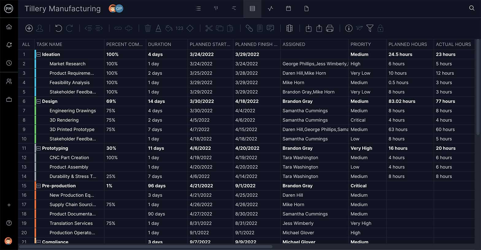
Project managers make use of project management software to lay out and execute a work breakdown structure. When used in combination with a Gantt chart that incorporates WBS levels and task hierarchies, project management software can be especially effective for planning, scheduling and executing projects.
ProjectManager is an online work management software with industry-leading project management tools like Gantt charts, kanban boards, sheets and more. Plan using WBS levels in our tool, then execute with your team via easy-to-use kanban boards and task lists. Try it for free today.
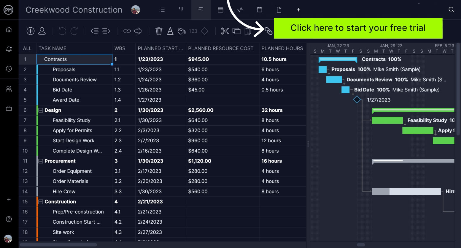
ProjectManager’s online Gantt charts feature a column for the WBS code— learn more
Making a WBS is the first step in developing a project schedule . It defines all the work that needs to be completed (and in what order) to achieve the project goals and objectives. By visualizing your project in this manner, you can understand your project scope, and allocate resources for all your project tasks.
A well-constructed work breakdown structure helps with important project management process groups and knowledge areas such as:
- Project Planning, Project Scheduling and Project Budgeting
- Risk Management, Resource Management, Task Management and Team Management
In addition, a WBS helps avoid common project management issues such as missed deadlines, scope creep and cost overrun, among others.
In other words, a work breakdown structure serves as your map through complicated projects. Your project scope may include several phases or smaller sub-projects—and even those sub-projects can be broken down into tasks, deliverables, and work packages! Your WBS can help you manage those items, and gain clarity into the details needed to accomplish every aspect of your project scope.

Get your free
WBS Template
Use this free WBS Template for Excel to manage your projects better.
Now that we’ve gone through the definition of a WBS and learned why they are a great project management tool, let’s take a look at a work breakdown structure example.
For our WBS example, we’ll be creating a work breakdown structure to lay down the work plan for a commercial building construction project. This is potentially a complex project, but a WBS chart will take that complexity and boil the project scope down to simpler tasks to make the project manageable.
Study the phase-based work breakdown structure example of a construction project below:
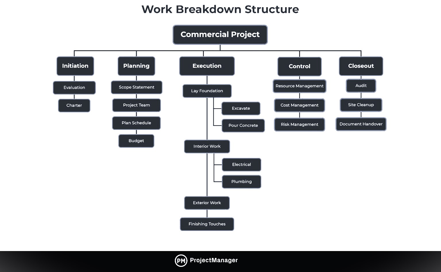
At the top of the work breakdown structure is your final deliverable (in this instance, the construction project). Immediately beneath that is the next WBS level, which are the main project phases required to complete the project. The third and lowest level shows work packages . Most WBS charts have 3 levels, but you can add more depending on the complexity of your projects.
Each of those five project phases—initiation, planning, execution, control and closeout, also act as control accounts and branch off the main deliverable at the top. Once decided, they are then broken down into a series of deliverables. For example, the initiation phase includes site evaluation work and creating the project charter.
You’ll also need a work package to go with each of those project deliverables. In the execution phase of our construction example, we can look at the interior work deliverable. That deliverable is divided into two work packages, which are installing the plumbing and setting up the electricity.
The WBS, when created as thoroughly as possible, is the roadmap to guide you to the completion of what would seem to be a very complicated project scope. However, when broken down with a WBS, project planning, scheduling and resource planning suddenly become much more manageable.
There are two main types of WBS: deliverable-based, and phase-based. They depend on whether you want to divide your project in terms of time or scope.
Deliverable-Based Work Breakdown Structure
A deliverable-based WBS first breaks down the project into all the major areas of the project scope as control accounts and then divides those into project deliverables and work packages.
Here’s an example of a deliverable-based WBS that’s taken from our free work breakdown structure template. Download the template today to practice building your own work breakdown structure in Excel.
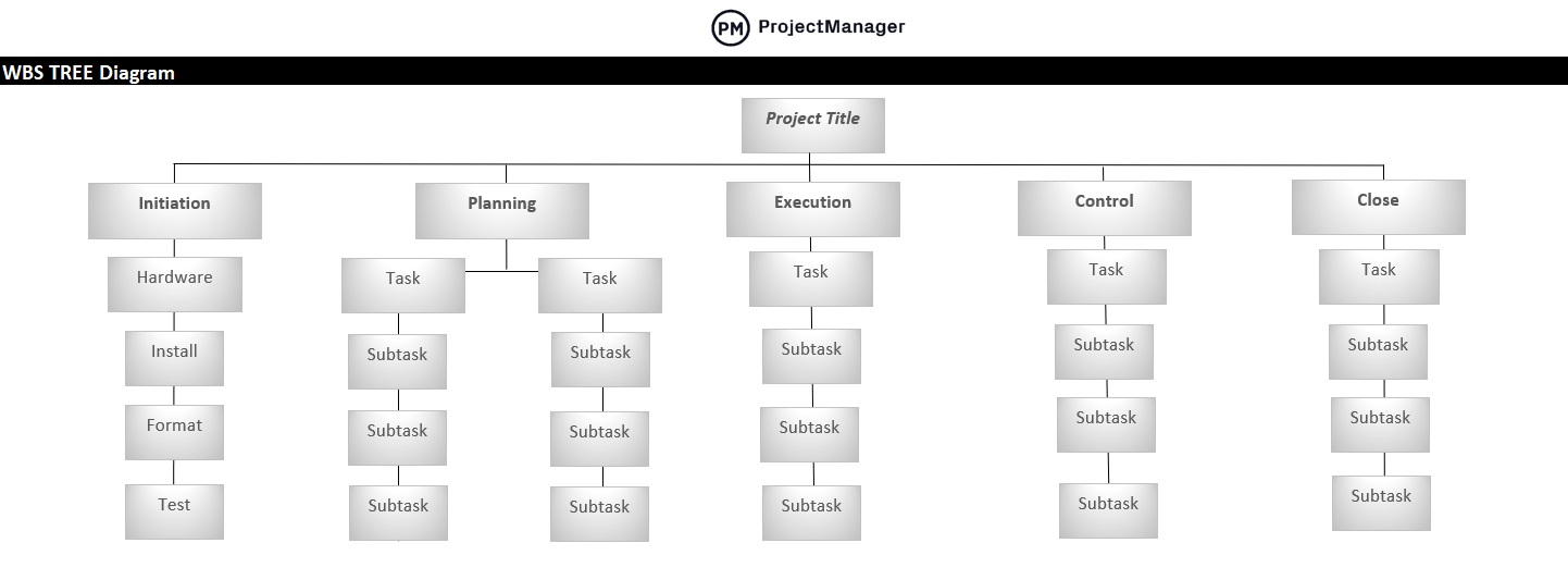
A deliverable-based WBS example showing control accounts, work packages and tasks.
Phase-Based Work Breakdown Structure
The phase-based WBS displays the final deliverable on top, with the WBS levels below showing the five phases of a project (initiation, planning, execution, control and closeout). Just as in the deliverable-based WBS, the project phases are divided into project deliverables and work packages. Our previous graphic in the “Work Breakdown Structure Example” section contained a phase-based WBS example.
Types of WBS Charts
Once you’ve chosen a deliverable-based or phase-based WBS, you can also choose between different types of WBS diagrams. Let’s take a look at the main types of work breakdown structure charts.
Work Breakdown Structure List: Also known as an outline view, this is a list of work packages, tasks and deliverables. It’s probably the simplest method to make a WBS, which is sometimes all you need.
Work Breakdown Structure Tree Diagram: The most commonly seen version, the tree structure depiction of a WBS is an organizational chart that has all the same WBS elements of the list (phases, deliverables, tasks and work packages) but represents the workflow or progress as defined by a diagrammatic representation.
Work Breakdown Structure Gantt Chart: A Gantt chart is both a spreadsheet and a timeline. The Gantt chart is a WBS that can do more than a static task list or tree diagram. With a dynamic Gantt chart, you can link dependencies, set milestones, even set a baseline. This is the most common version in project management software.
Build a work breakdown structure Gantt chart diagram in ProjectManager in just a matter of minutes. Get started for free today.
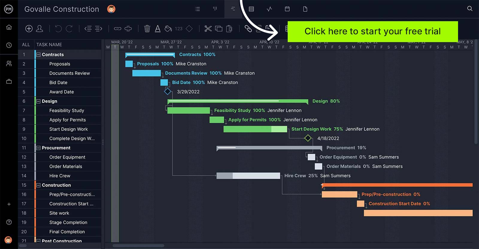
A Gantt chart with WBS codes in ProjectManager. Learn more
A typical project work breakdown structure is made up of several key components. We’ll use our WBS example above to identify each of the main WBS elements.
- WBS Dictionary: A WBS dictionary is a document that defines the various WBS elements. It’s an important component of a WBS because it allows the project participants and stakeholders to understand the work breakdown structure terminology with more clarity.
- WBS Levels: The WBS levels are what determines the hierarchy of a WBS element. Most work breakdown structures have 3 levels that represent the project’s main deliverable, control accounts, project deliverables and work packages.
- Control Accounts: Control accounts are used to group work packages and measure their status. They’re used to control areas of your project scope. In our example, the execution project phase could be a control account because it has several deliverables and work packages associated with it.
- Project Deliverables: Project deliverables are the desired outcome of project tasks and work packages. In our WBS example, we can observe some examples of project deliverables such as the project budget or interior work. Both of them are the result of smaller tasks and work packages.
- Work Packages: As defined by the project management institute (PMI) in its project management body of knowledge book (PMBOK) a work package is the “lowest level of the WBS”. That’s because a work package is a group of related tasks that are small enough to be assigned to a team member or department. As a project manager, you can estimate costs and duration of these work packages, which makes them an essential WBS element.
- Tasks: Your tasks make up your work packages and therefore, your project scope. A WBS will help you define each task requirements, status, description, task owner, dependencies, and duration.
If you prefer a visual and verbal explanation of this information on work breakdown structures, watch this video.
To create a WBS for your project, you’ll need information from other project management documents. Here are six simple steps to create a work breakdown structure.
1. Define the Project Scope, Goals and Objectives
Your project goals and objectives set the rules for defining your project scope. Your project scope, team members, goals and objectives should be documented on your project charter .
2. Identify Project Phases & Control Accounts
The next level down is the project phases: break the larger project scope statement into a series of phases that will take it from conception to completion. You can also create control accounts, which are task categories for different work areas you want to keep track of.
3. List Your Project Deliverables
What are your project deliverables ? List them all and note the work needed for those project deliverables to be deemed successfully delivered (sub-deliverables, work packages, resources, participants, etc.)
4. Set WBS Levels
The WBS levels are what make a work breakdown structure a “hierarchical deconstruction of your project scope”, as defined by the project management institute in its project management body of knowledge book (PMBOK). You’ll need to start at the final project deliverable and think about all the deliverables and work packages needed to get there from the start.
5. Create Work Packages
Take your deliverables from above and break them down into every single task and subtask that is necessary to deliver them. Group those into work packages.
6. Choose Task Owners
With the tasks now laid out, assign them to your project team. Give each team member the work management tools , resources and authority they need to get the job done.
Work breakdown structure software is used to outline a project’s final deliverable and define the phases that are necessary to achieve it.
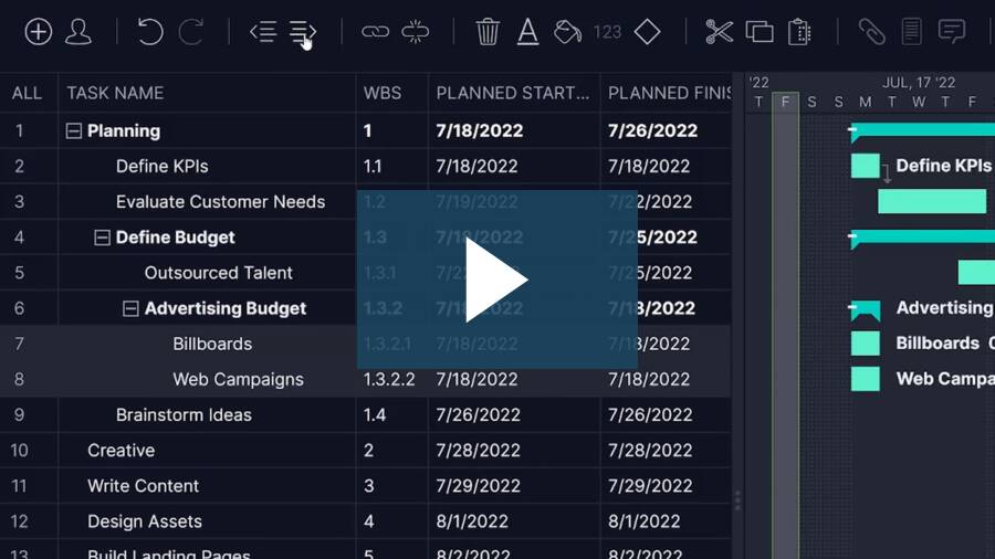
Software facilitates the process in several different ways. Some use a network diagram and others use a Gantt chart. All of them, however, are a visual representation of the project, literally breaking down the various stages and substages needed to assemble the final project deliverable.
There are many types of work breakdown structure software available, so when you’re looking for one to help you plan your project, be sure it offers these features:
Break Tasks Down
Deliverables are important to define, as are the tasks that get you there—but most tasks require being broken down further in order to complete them. That’s where subtasks come in. They’re part of a more complex task, and you want that feature in your WBS software.
Link Dependent Tasks
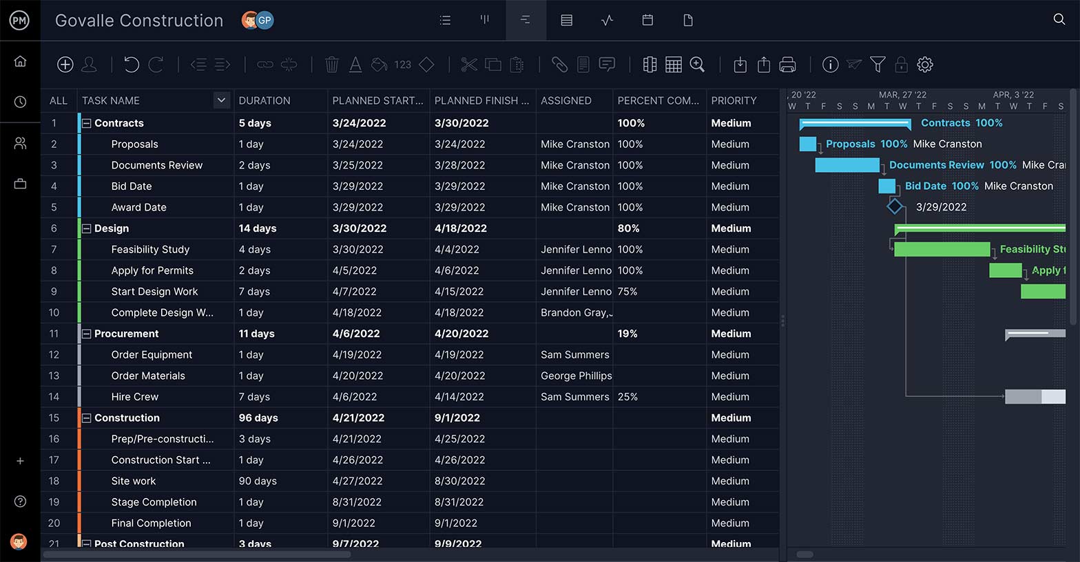
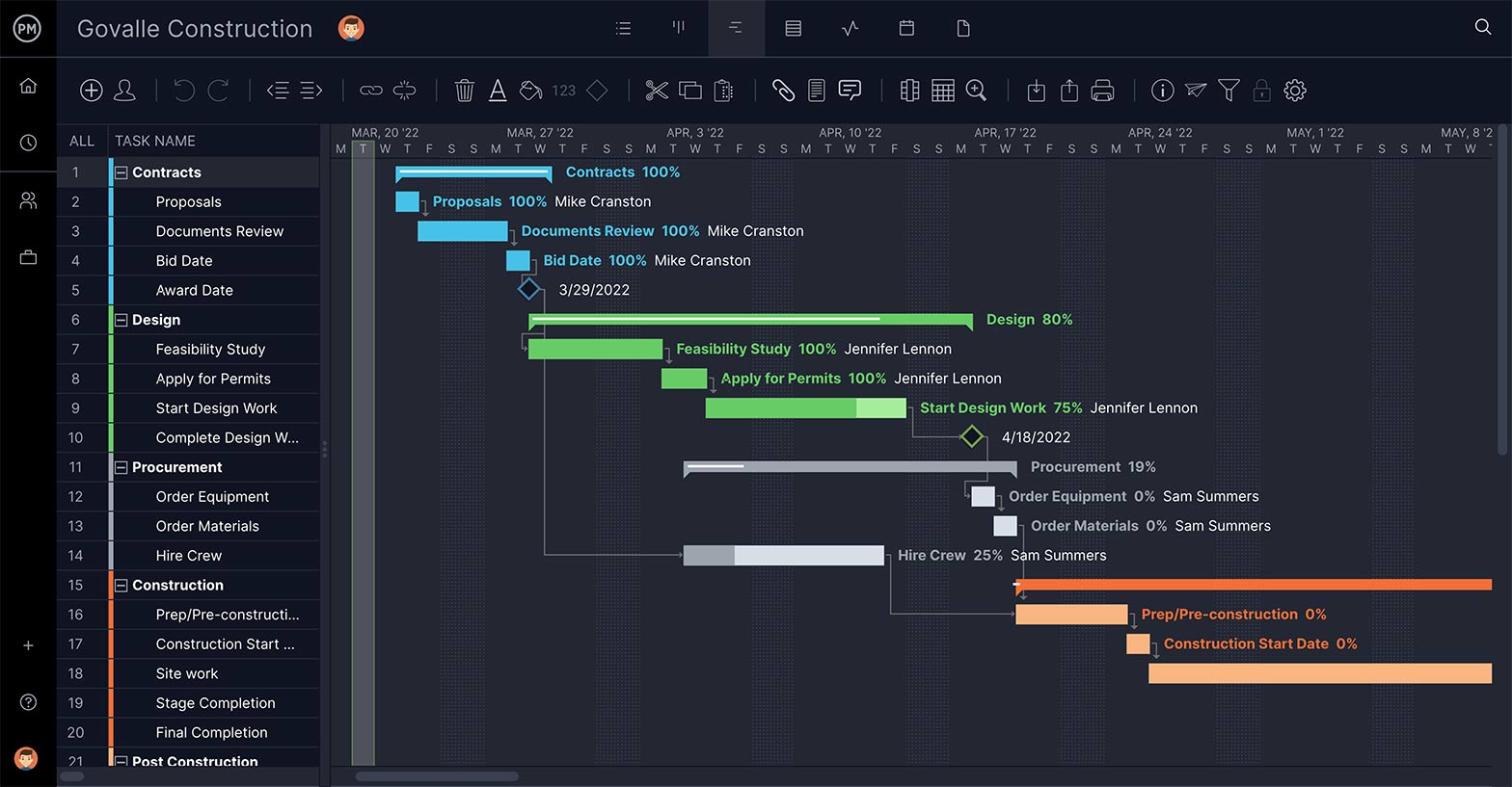
Not all tasks are the same. Some can’t start or stop until another has started or stopped. These dependent tasks can create a bottleneck later in the project’s execution phase, unless you identify them early. Having a task dependency feature is essential.
Set Task’s Priority and Duration
The point of WBS software is to build a feasible schedule. Therefore, you need features that feed into this process by defining the priority of the task, so you know which phase it goes with; as well as describing the task and estimating how long it will take to complete.
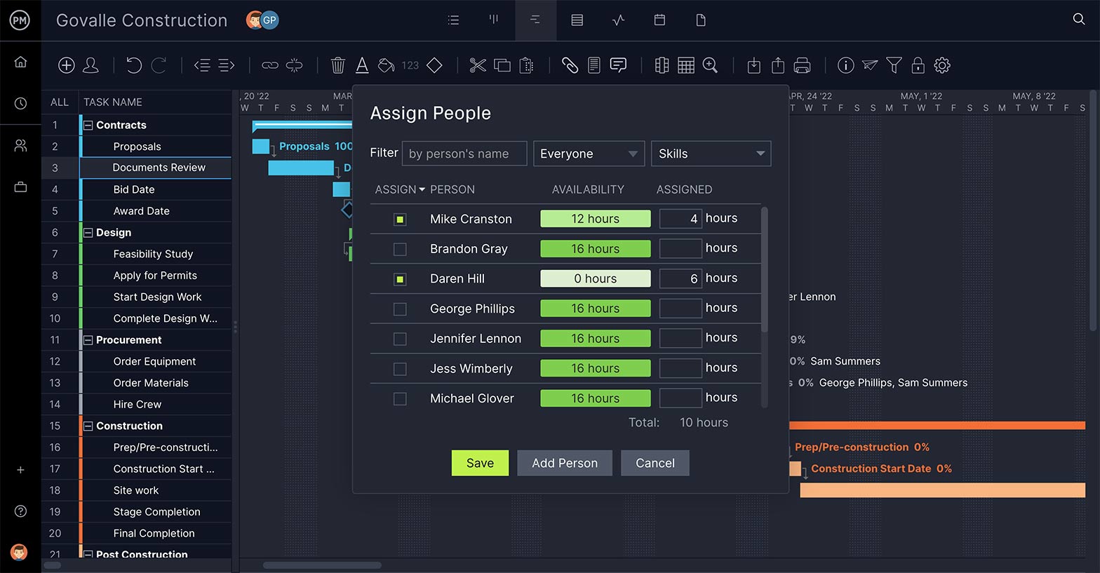
Keep Your Team Working
The WBS sets up your tasks and deliverables, but once the project is in the execution stage, it’s key that you have a way to allocate resources to your team to keep the tasks moving as planned. That includes a feature to make sure their workload is balanced.

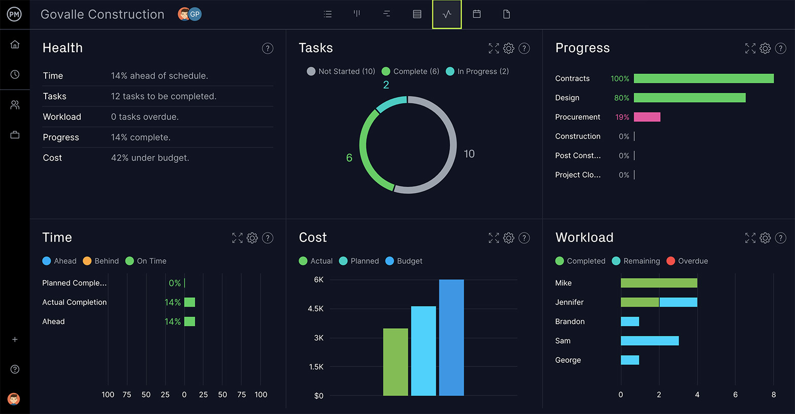
Get a High-Level View
Being able to monitor your progress is what keeps your project on schedule. A WBS software sets up the plan and you must have features to maintain it throughout all the phases of the project. Dashboards can give you a view of the landscape across several metrics.
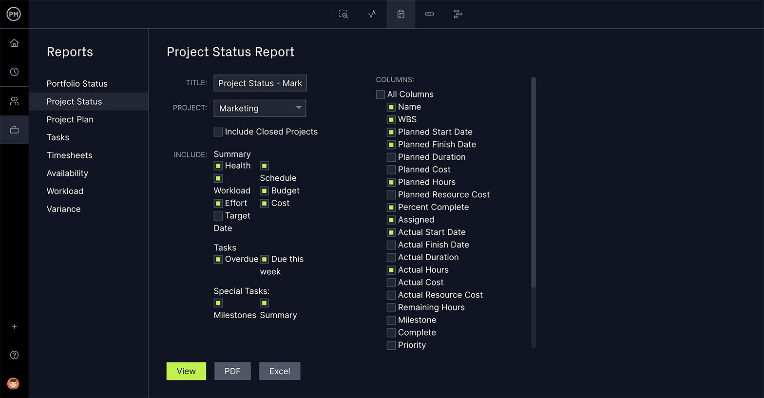
Make Better Decisions
As you move from the planning to the execution stage, you’ll need a reporting feature that can deliver critical project data on progress and performance. This information will feed your decision-making and help you steer the project to a successful conclusion.
The purpose of work breakdown structure software in project management is to organize and define the scope of your project. Using ProjectManager’s online Gantt charts to build your WBS is not only more efficient, it dovetails into every other aspect of your project, because of our robust suite of project management features.
Here’s a quick summary of how to create a WBS using a Gantt chart. Sign up for a free trial of our software and follow along !
1. Identify Project Deliverables
There are 5 stages in the project life cycle, initiation, planning, execution, monitoring and closure. Each of them produces deliverables that are required to produce the final deliverable, which is the completion of your project.
Identify the phases in your project to create more than a mere task list. Set them apart with our milestone feature on the Gantt chart tool. They can also be color coded to better differentiate the phases.
2. List Subtasks, Describe Tasks & Set Task Owner
Subtasks are part of a larger, more complex task. In this case, your WBS work packages are perfect for this feature. Add summary tasks or work packages above the related tasks, which can be your project phases or project deliverables, depending on your WBS type preference and indent them. The image below shows our WBS example represented on a Gantt chart, showing the project phases and work packages associated with them.
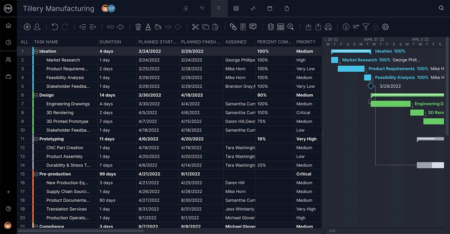
3. Link Dependencies
Task dependencies are tasks that cannot start until another is finished or started. Link tasks that are dependent on one another by dragging one to the other. We link all four types of task dependencies. By identifying these tasks at this stage, you’ll avoid bottlenecks during execution.
4. Set Resources & Costs
Resources are anything that you need to complete the project phases, deliverables and work packages. They range from the people on your team to materials, supplies and equipment. Your WBS allows you to break down your project scope into work packages so that you can estimate resources and costs.
5. Add Start & End Dates & Estimated Completion
Every task has a start and an end date. Add the date when the task needs to start in the planned start date column and when it should be completed in the planned finished date. There’s also an estimated completion column for the amount of time you plan for the task to take.
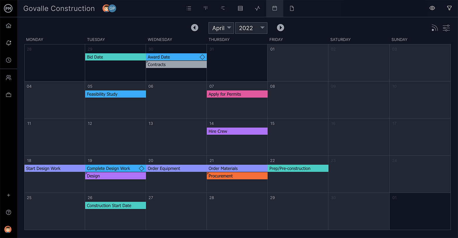
6. Track Status of Control Accounts & Work Packages
Tracking is how to know if a project is performing as planned. That’s why a WBS has control accounts and work packages. When speaking of tasks, tracking tells you multiple things: logged hours, costs, priority, new communications, the percentage complete and how its actual progress compares to your planned progress.
7. Write Notes
Having a section in which to jot down notes is always advisable. While the WBS is thorough, there might be something you need to address that doesn’t fit into its rigid structure.
8. Generate Reports
Project reports pull data from the project to illuminate its progress, overall health, costs and more. Generate a report on your WBS by using our reporting tool. Our reports summarize your project data and allow you to filter the results to show just want you want. Reports can also be shared with stakeholders.

If you’re not ready to take the plunge and use ProjectManager’s work breakdown structure software, but you’re still interested in seeing how using this tool can help you construct a sturdier plan for your next project, don’t worry. We have an intermediate step you can take.
We also have a library of free project management templates , including a free WBS template, to get you started off right.
If you decide to try out our project management software, we offer a free 30-day trial. You can upload the project work breakdown structure template into ProjectManager, and it automatically creates a new project in our software. Now you can use that template to plan, schedule, monitor and report on your project.
Because our software is cloud-based, all your data is collected and displayed in real time. This makes us different from on-premises project management software like Microsoft Project . We take your WBS and make it more dynamic with our online planning tools .
There are many ways in which you can use a work breakdown structure to help you manage work. Here are three common examples of how to use a WBS for different purposes.
Scope of Work
A scope of work is a comprehensive document that explains your project scope, which is all the work to be performed. A WBS is the perfect tool to break down the scope of a project into work packages that are easier to control. On top of that, a work breakdown structure allows you to easily identify milestones, deliverables and phases.
Statement of Work
A statement of work is a legally binding document between a client and the organization who’s responsible for executing a project. It details project management aspects such as the timeline, deliverables, requirements of the project.
A work order is similar to a statement of work, but it’s main purpose is to show the costs associated with each task. A WBS is essential for an accurate cost estimation.
As you’re working on your WBS it is helpful to maintain some best practices. Here are some things to keep in mind.
- 100% Rule: This is the most important work management principle to construct a WBS. It consists in including 100% of the work defined by the project scope, which is divided into WBS levels that contain control accounts, project deliverables, work packages and tasks. This rule applies to all the levels of the WBS, so the sum of the work at a lower WBS level must equal the 100% of the work represented by the WBS level above without exception.
- Use Nouns: WBS is about deliverables and the tasks that will lead to your final deliverable. Therefore, you’re dealing more on the what than the how. Verbs are great for action, and should be used in your descriptions, but for clarity, stick to nouns for each of the steps in your WBS.
- Be Thorough: For a WBS to do its job, there must be no holes. Everything is important if it’s part of the course that leads to your final deliverable. To manage that schedule, you need a complete listing of every task, big and small, that takes you there.
- Keep Tasks Mutually Exclusive: This simply means that there’s no reason to break out individual tasks for work that is already part of another task. If the work is covered in a task because it goes together with that task, then you don’t need to make it a separate task.
- Go Just Deep Enough: You can get crazy with subtasks on your WBS. The WBS has to be detailed, but not so deep that it becomes confusing. Ideally, think maybe three or five at most levels.
All our tools are geared to making your project more efficient and effective. See for yourself by starting your free 30-day trial of our software.
Start My Free Trial
Work Breakdown Structure Resources
- Scope of Work Template
- Gantt Chart Template
- Work Plan Template
- Work Schedule Template
- Statement of Work Template
- Work Order Template
- Project Management Trends (2022)
- How to Make a Resource Breakdown Structure
- 5 Project Management Techniques Every PM Should Know
- Cost Estimation for Projects: How to Estimate Accurately
- Sample Project Management Flow Chart
- Sample Project Plan For Your Next Project
Start your free 30-day trial
Deliver faster, collaborate better, innovate more effectively — without the high prices and months-long implementation and extensive training required by other products.

Work Breakdown Structure (WBS): The Complete Guide
Approx reading time:
Last updated on 11th April 2024
Work Breakdown Structure (or WBS, as it’s sometimes known) is about dividing a project into smaller, more digestible chunks, making it easier to plan, execute, and monitor.
In this guide, we’ll cover everything you need to know about work breakdown structures: what they are, how to create them, and how to use them effectively in your project planning.
We’ll also provide some templates and examples to get you started. So let’s dive in!
What is a work breakdown structure?
A work breakdown structure is a planning tool used by project managers to break down the work of a project into smaller, more manageable ‘pieces’ in order to make it easier to track progress – as well as identify potential issues.
As an organisational tool, WBS helps to assign roles for each task and subtask and define who’s responsible for what.
Typically created from the project scope , a WBS lets teams map out all tasks that need to be completed from beginning to end, starting with the larger activities and breaking them down into more granular detail until every element of the project has been accounted for.
With its flexibility and scalability, this popular planning tool can easily be modified along the way to adjust for changes or environmental factors that arise during the lifetime of a project.
The benefits of using a WBS
So, we’ve established that a work breakdown structure is an incredibly useful tool for project managers. What are the actual benefits of working in this way?
1. Improved project planning
A WBS breaks down complex projects into smaller, more manageable tasks, making it easier to plan and schedule the work that needs to be completed.
By identifying all the stuff that needs to be done, you can create a more accurate project plan, including timelines, milestones, and deliverables – keeping your entire project running smoothly and optimising chances of success.
2. Better resource allocation
With a detailed WBS, you can identify the specific resources needed for each task, including people, equipment, time and materials.
This lets you allocate resources more efficiently and effectively – ensuring that everyone and everything is being used to their fullest potential.
3. Greater project control
A work breakdown structure provides a clear and comprehensive overview of the project, allowing you to monitor progress, identify potential issues, and make necessary adjustments as issues arise.
By breaking the project down into smaller pieces, you can track progress more easily and keep everyone on the same page.
4. Enhanced communication
A WBS can serve as a valuable communication tool, since it lets you share project information with team members, stakeholders, and other relevant parties.
By presenting the project in a clear, structured format, you can facilitate communication and ensure that everyone understands what needs to be done and when.
People can grasp not only their own role in the bigger picture of your project, but also understand what others are working on.
5. Improved risk management
With a work breakdown structure, you can identify potential risks and develop strategies to mitigate them.
By breaking the project down into smaller pieces, you can identify areas where risks are more likely to occur and take steps to address them before they become major issues.
The different types of work breakdown structure
Further underlining the flexibility of this way of working, there are a variety of different types of WBS to be used and adapted depending on the needs of your project.
1. Deliverable-oriented WBS
This type of WBS focuses on the end deliverables of the project and breaks them down into smaller, more manageable tasks. Each task is assigned to a specific team or individual responsible for completing it.

WORKS BEST FOR: Projects with clearly defined outcomes.
2. Phase-oriented WBS
This type of WBS breaks down the project into phases, with each phase representing a major milestone or objective. Each phase is further broken down into smaller tasks, allowing for better project management and monitoring.

WORKS BEST FOR: Projects with distinct stages.
Each phase would then be given its own set of tasks and assigned to specific people.
3. Organisational-oriented WBS
This type of WBS is based on the organisational structure of the project team. Tasks are grouped according to the team or department responsible for completing them, making it easier to allocate resources and track progress.

WORKS BEST FOR: Projects with multiple departments or stakeholders involved.
4. Activity-oriented WBS
This type of WBS breaks down the project into specific activities or tasks that need to be completed, regardless of the end deliverable. Each activity is assigned to a specific team or individual responsible for completing it.

WORKS BEST FOR: Projects with many interdependent tasks.
5. Hybrid WBS
This type of WBS combines two or more of the above types, depending on the needs of the project. For example, a hybrid WBS may include a phase-oriented WBS for overall project management, with an activity-oriented WBS for specific tasks or deliverables.
WORKS BEST FOR: Projects where you have a ‘mix’ of any or all of the other types of WBS and need to use a highly customised WBS to suit the needs of the project team.
A hybrid WBS would be necessary in this project because it would allow for both deliverable-based and phase-based management, as well as departmental management.
This would provide a more comprehensive and flexible structure for managing the project, ensuring that all deliverables are completed on time and within budget while also allowing for more efficient departmental coordination and resource allocation.
In essence a hybrid WBS offers the best of both worlds – a high-level overview of the project’s phases and deliverables, as well as a more detailed breakdown of the tasks and responsibilities within each department.
How to Create a WBS
Developing a WBS isn’t difficult – all it takes is understanding the basics of project management and following a few steps.
1. Identify the major deliverables
The first step is to identify the major deliverables or outcomes that the project aims to achieve. These are usually the key objectives or milestones of the project.
2. Break down deliverables into sub-deliverables
Once the major deliverables have been identified, break them down into smaller, more manageable sub-deliverables. This step involves breaking down the major objectives into smaller, more specific tasks that need to be completed to achieve them.

3. Continue breaking down until you reach manageable tasks
Continue breaking down the sub-deliverables into smaller and more manageable tasks until you have reached a level of detail that is sufficient for project planning and management. This level of detail will depend on the complexity and size of the project.
4. Organise the tasks
Organise the tasks into a hierarchical structure that shows the relationship between the different tasks. This structure will help in project planning and tracking progress.
5. Assign resources and estimate time
Assign resources and estimate the time required to complete each task. This will help in determining the project schedule and budget.
6. Review and refine
Review and refine the WBS to ensure that it accurately reflects the scope of the project and that all necessary tasks have been included.
7. Use the WBS as a reference
Once the WBS has been created, use it as a reference tool throughout the project to ensure that all tasks are completed as planned and that the project stays on track.
Work Breakdown Structure: A Summary
To recap, creating a work breakdown structure (WBS) is a critical step in planning and managing a project.
By breaking down a project into smaller, manageable deliverables, the project team can organise their work, allocate resources effectively, and track progress more easily.
If you’re looking for the best way to manage your projects, then why not try using Project.co ? With Project.co, you can easily create your project, set up tasks, invite your team, allocate tasks to team members, and give them deadlines – all in one central location. This allows you to have a clear overview of where things are at in your project and who is working on what at every stage.
Project.co makes project management simple, streamlined, and efficient, helping you to get your project completed on time and within budget.
So why not give it a try? Sign up today and get started right away.

Written by Samantha Ferguson
⭐️ All your work in one place
🗓 Never miss a deadline
🗂 Never lose a file
🏅 Simple for your clients
⚡️ Powerful for your team
Create your account
Create your account and experience the magic of having all your information and communication in one place. Never miss a deadline, have a happier team and happier customers.
- Become a partner
- Customer stories
- Gantt chart
- Roadmapping
- How-tos and guides
- Project management
- GanttPRO news
- Microsoft Project Tutorial
Work Breakdown Structure Examples (WBS) that You Can Use as References in 2024
Audio version:
The concept of a work breakdown structure (WBS) is widely used to represent the project’s scope and deliverables in a hierarchical way.
Sometimes the structure may seem confusing for beginners who are new to project management. Therefore it’s crucial for any project manager to always have a reliable work breakdown structure example at hand.
In this post, we share some simple work breakdown structure examples that will help you to deconstruct your project production processes in different spheres into manageable components.
- Choosing a project work breakdown structure example .
- WBS example for software development .
- WBS construction project example .
- WBS healthcare example .
- Example of a work breakdown structure WBS for an event .
- Example of WBS for opening a restaurant .
- Find the best WBS for your project .
The graphical nature of a WBS is typically visualized as a result-oriented tree that covers all project procedures in an organized way. This is what differs WBS from other project management charts .
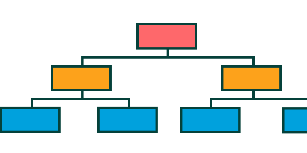
A tree view is not the only representation of a work breakdown structure. You can also find the examples of creating a WBS in the form of a horizontal hierarchical list, which is most successfully visualized by a Gantt chart.
This kind of WBS creator provides a convenient system with the numbering of tasks and subtasks. The essence of the breakdown is essentially the same, but the representations are different. You’ll see this in more detail in the examples below.
A work breakdown structure is the foundation of project planning alongside a Gantt diagram. Therefore, to excel your project management skills , it’d be also good for you to know how to read a Gantt chart .
Project managers apply these two approaches to divide complex projects to get things done faster and efficiently. Breaking their projects down into smaller parts means that work can be performed simultaneously by different employees. It boosts productivity and improves project management.
There are many examples, templates, and project management tools that assist in creating a visually appealing work breakdown structure. Let’s dive into some common samples from various spheres that will allow you to select the best WBS work breakdown structure example for your needs.
Choosing a project work breakdown structure example
A work breakdown structure can be different for each project. Trying to find the most appropriate example of a work breakdown structure in project management, you should spend some time experimenting and see which WBS performs best for your team. There is no need to rush here, as the result of the entire project will depend on your choice.
You’ve probably heard about how to make a WBS in Excel . You can also find a project work breakdown structure example visualized with the help of a flowchart, a spreadsheet, or can create a Gantt chart online . However, the main idea is to visualize the hierarchy of your projects and make progress clear to everyone involved.
For example, you have a project that consists of two global parts or key tasks. These tasks will contain certain subtasks that must be followed strictly one by one. These subtasks can also have a list of activities in a smaller hierarchy. All this makes up a WBS structure.
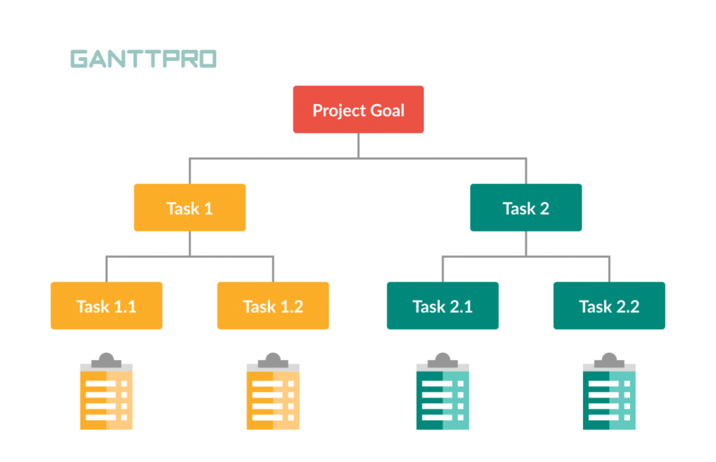
This project management work breakdown structure example can be easily built with the help of an online Gantt chart. This way is one of the most reliable and demanded among modern project managers.
The diagram will include both your project work hierarchy and a timeline. Therefore, you will be able to link task dependencies, mark milestones, and track when each activity is supposed to start and end.
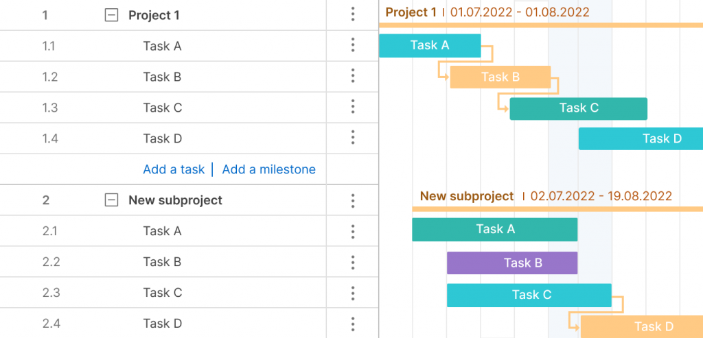
It means that using any available work breakdown structure in project management example, you’ll be able to generate your own WBS without headache.
Now it’s time to list some common cases where you can apply WBS. Let’s start with a work breakdown structure example for project management in IT, and end with the example of a work breakdown structure for a project related to some creative project management activities.
Work breakdown structure example for software development
Software development is one of the most popular areas in terms of using WBS.
Let’s consider a software development work breakdown structure example related to creating a new e-commerce application. Experienced project managers usually generate such WBS structures using a Gantt chart (this is where GanttPRO is a perfect helper), but many still apply simple tools, for example, an Excel template.
A new e-commerce site must be executed impeccably and clearly, since there are so many competitors on the market. Therefore the work breakdown structure software development example must also be clear, concise, and detailed.
We will show how this can look like in a classic tree view and in a variant on a Gantt chart with numbering and a horizontal list hierarchy.
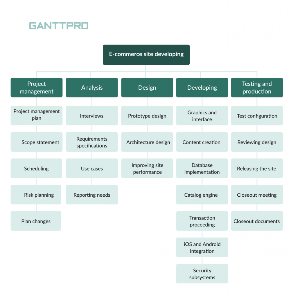
As you see, this result-oriented tree work breakdown structure example of a software project focuses on the project management, analysis, designing, developing, and testing stages.
- Project management . The first stage of our work breakdown structure for software project example includes planning, defining scope, scheduling, risk management, and work with possible plan changes.
- Analysis. At this stage, project teams conduct required interviews, work on requirements specifications, and prepare use cases.
- Design is one of the most essential parts of our software development work breakdown structure example. Here, you should care about the prototype design, architecture design, and site performance improvements.
- Developing. This is typically one of the most active phases of software development, so you will need to thoroughly work on developing the new e-commerce site and care about all the details, meaning graphics and interface, content creation, database implementation, catalog engine, transaction processing, iOS and Android integration, security, and other important issues.
- Testing and production are what end the process. This is when test configuration, reviewing design, releasing the site, closeout meetings, and preparing closeout documents happen.
This example of a work breakdown structure WBS in project management for software development needs is pretty clear and simple to be implemented with the help of an online Gantt chart. You can check this by opening your project in GanttPRO and visualizing your WBS there.
Look at how convenient the tasks and subtasks are displayed on a Gantt chart in GanttPRO:
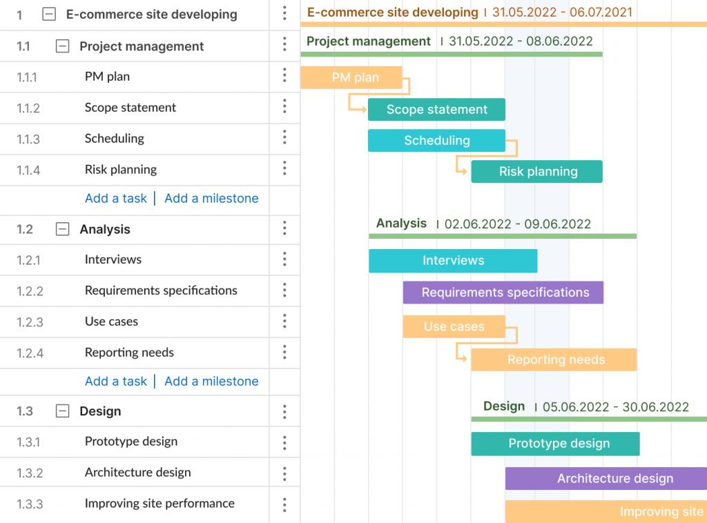
It’s time to move on to the next example in another popular professional area.
Work breakdown structure construction project example
When millions are on the line in construction project management, avoiding costly mistakes becomes your priority. That is why, your vital objective is to prepare an ideal WBS, referencing any reliable work breakdown structure construction project example . Again, you can create it using a professional tool or even utilize an Excel WBS template.
For better understanding, let’s analyze a work breakdown structure example for a construction project related to building a cottage. This is a popular case, as people round the world constantly seek a breakdown structure for building a house example. Such projects usually require detailed preparation and careful planning.
This example of a work breakdown structure for a construction project demonstrates that all the elements are listed under the WBS levels. The lowest levels represent the project deliverables, and all activities and tasks will be grouped under these lowest levels.
- Level 1 is the overall project.
- Level 2 is the key stage of this project.
- Levels 3, 4, and 5 represent the major and minor deliverables.
Let’s look at all these levels on a tree-like WBS in detail.
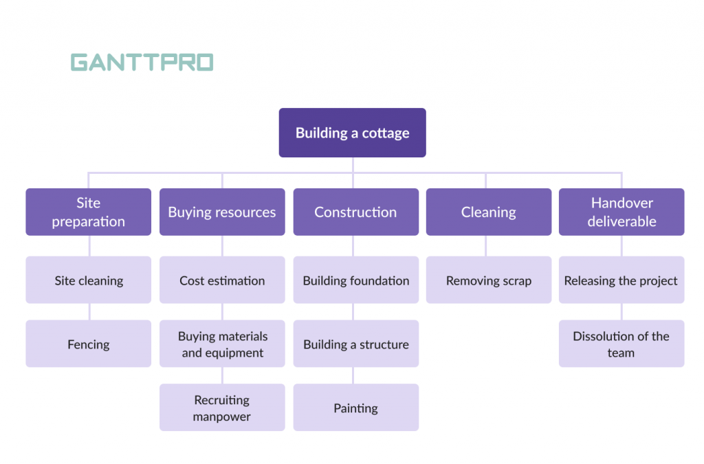
- Site preparation. It’ll all start with the site cleaning. The nearby area should be ready for all upcoming activities. It will take some time. After that, you will need secure fencing in order to carry out all the internal work.
- Buying resources . The next stage of our construction work breakdown structure example includes estimating costs, purchasing the necessary materials and construction equipment, and recruiting manpower.
- Construction . This is one of the most important steps in the process of building the cottage, as it relates to building a foundation and various structures. Painting works are also included into this part of the WBS.
- Cleaning . After all construction work, you will need to remove scrap and unnecessary building materials.
- Handover deliverable . Our work breakdown structure for construction project examples will end with the release of the cottage and the dissolution of the team.
Nothing difficult, right?
Now look at how a WBS can be visualized in GanttPRO.
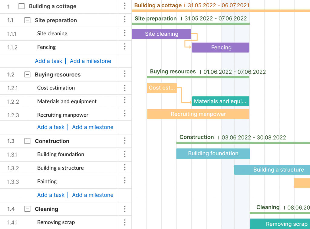
A friendly timeline and dozens of useful features make your WBS a perfect visual tool. This fully explains the fact that so many project teams around the world use GanttPRO templates as the example of a work breakdown structure for housing construction projects. It really makes life easier and simplifies many processes, saving valuable time.
Meanwhile, we are moving to the next sphere and another interesting case.
Example of a work breakdown structure for opening a restaurant
This type of a work breakdown structure will help you to track processes to eliminate unnecessary activities and expenses.
The main activities will relate to marketing research, design, construction, installation, resource management, advertisement necessary equipment, etc.
So, the tree-like example of a work breakdown structure for opening a restaurant may look like this:
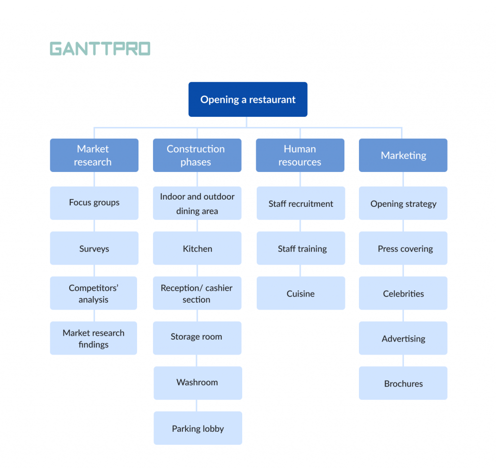
- Market research . The initial objectives of a project manager in a restaurant will be related to working with focus groups, different surveys, competitors’ analysis, and market research findings. This will give a clear picture of the current state of the market.
- Construction phases. At this stage, the manager should care about constructing the restaurant according to the concept and required design. It is important to think over the design of the indoor and outdoor dining area, the kitchen, the reception and cashier section, the storage room, the washroom, and the parking lobby.
- Human resources. The restaurant staff consists of managers, chefs, waiters, cleaners, security officers, receptionists, and other roles. It’s crucial to care about timely staff recruitment and training. The quality of restaurant cuisine must also be controlled.
- Marketing . Any opening event contains many marketing activities, including preparing the opening strategy, work with press and celebrities, advertising, designing brochures, and other tasks.
What do you think about this work breakdown structure restaurant example? Perhaps, you’d like to add some levels or essential blocks. It’s easy to do, choosing a horizontal hierarchy and a list view of your WBS. This is where a Gantt chart comes to the rescue again.
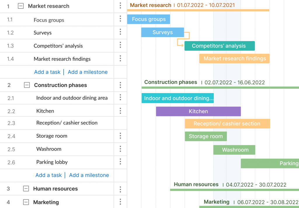
Don’t forget that you can easily create such an appealing work breakdown structure using GanttPRO Gantt chart maker.

Advanced project management and planning
Create a work breakdown structure with a handy Gantt chart.
The only thing that remains is to remind you how to add a WBS feature in your GanttPRO project.
You can actually create as many projects as you need with an unlimited number of tasks.
Generate your list of tasks and subtasks. By adding a WBS field from the list, you will be able to order your task list to visualize the hierarchy you want.
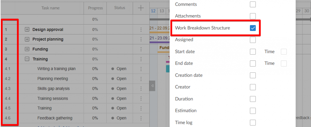
Find the best work breakdown structure example for your project
A WBS has proved to be one of the tools that provides the base of successful project management.
Knowing and understanding this tool is extremely useful, especially if you want to get a PMP certification . Therefore you should have an efficient work breakdown structure example at hand to be always ready to work with any project plan.
You can organize your WBS as a Gantt diagram that links task dependencies and reflects project milestones. Available Gantt chart examples will help you to better understand all the features of this project management diagram.
We hope that by this part of the article you have already appreciated all the advantages of GanttPRO as a WBS software , because with its help you will be able to build handy and reliable work breakdown structures with ease.
Use GanttPRO to generate a WBS for:
- Software development.
- Construction.
- Healthcare.
- Event planning.
- Opening restaurant, and many other spheres and professional areas.
After all, you can utilize such a structure for personal purposes and special events – to plan your own anniversary or prepare for exams. The strength of the WBS lies in its versatility and adaptability to various purposes. Feel free to discover it!
Paolo Kukhnavets
Paolo writes about the exciting world of project management, innovative tools, planning strategies, time management, productivity, and more. He has a professional journalism education, over ten years of writing experience, and a vast bag of enthusiasm to comprehend and learn new things every day. In his other life, he is addicted to traveling, gym, and sci-fi movies. He cycles and runs a lot.
More about project management — straight to your inbox
Good simple explanation of WBS
Thanks 😉 Feel free to also read the article about the top-5 WBS tools for project management needs: https://blog.ganttpro.com/en/work-breakdown-structure-wbs-software/
This made wbs so sample Thank you
Thanks for your comment. Have you read about the leading WBS software solutions on the market? Here’s the post https://blog.ganttpro.com/en/work-breakdown-structure-wbs-software/
simple and nice explanations
Thank you. Please also read about the WBS creator https://ganttpro.com/wbs-creator/ that will help you visualize similar examples and cases without headaches.
Join 800,000+ project managers!
Create Gantt charts in minutes with GanttPRO and reduce time spent on managing tasks by 40%
No credit cards required. No obligation.
Transform teamwork with Confluence. See why Confluence is the content collaboration hub for all teams. Get it free
- The Workstream
- Project management
- Work breakdown structure
Work breakdown structure (WBS) in project management
Browse topics.
If you ever feel like your project is spiraling out of control with slipped deadlines and missed tasks, a work breakdown structure (WBS) can help. A well-crafted WBS is your roadmap to success, breaking down projects into manageable pieces to ensure you assign tasks efficiently and don’t miss deadlines.
These tools ensure all objectives are clearly communicated throughout the company, keeping surprises to a minimum and preventing anyone from not knowing their role.
This article explains a WBS, its key components, and how you can create one for your project and transform your approach to project management .
What is a work breakdown structure (WBS)?
A WBS in project management is a hierarchical decomposition of a project into smaller components. It starts with the overall project goal at the top and then breaks things down into smaller, more efficient deliverables.
Each level of a work breakdown structure provides more detailed descriptions of project work, starting from the high level that defines the project goal. The next level outlines major deliverables, followed by sub-deliverables, and finally, the work packages.
Purpose of a WBS in project management
A WBS in project management organizes and defines the project scope by breaking it down into manageable sections. It sets a clear framework for project planning , execution, and control.
The WBS clearly outlines each task to help assign responsibilities. Each work package has enough detail to accurately predict resource requirements and durations, aiding in estimating costs and timeframes.
Use a WBS to keep track of project plan completion and ensure your project stays on track.
Gantt chart
A Gantt chart is a visual representation of the project life cycle. It lists tasks along a timeline, showing timeframes, dependencies, and progress. This tool is highly effective for teams that need clear instructions on the project schedule .
While it is not a WBS, you can combine it with one to achieve better planning and scheduling.
Deliverable-based WBS
A deliverable-based WBS focuses on the project's output. It breaks the project into major deliverables instead of phases. This is more useful for projects where the end product or the output is clear and distinct.
Kanban is a visual method for managing project work as it moves through a process. It uses cards on Kanban boards to represent tasks and columns to indicate different workflow stages.
This method is ideal for Agile projects and requires continuous monitoring and frequent adjustment.
Phase-based WBS
Unlike deliverable-oriented WBSs, a phase-based WBS divides the project according to its phases or stages. Each phase represents a major section of the project timeline , and all the phases break down into further tasks and activities.
This type is ideal for projects with well-defined stages, such as software development or construction.
Calendars in project management provide a time-based structure for the WBS. They help to ensure task completion within set timeframes. This method also helps keep track of deadlines, milestones, and resource availability.
The calendar method is best for projects with strict deadlines or fixed timeframes.
Key components of a work breakdown structure
Each component of a WBS serves a different purpose. They have specific roles and levels of detail. The highest level depicts the ultimate goal, and the lowest level defines specific details.
The key components of WBS include the following:
- Phases : Phases represent the major stages of the project life cycle. Each phase groups relevant activities and tasks.
- Tasks : Tasks are individual activities within each phase of a project.
- Subtasks : Each task splits into subtasks, allowing for precise planning and execution.
- Deliverables : Deliverables are tangible or intangible outputs resulting from the completion of tasks.
- Sub-deliverables : Sub-deliverables are smaller outputs that contribute to completing larger deliverables.
- Work packages : Work packages are the smallest units of work in a WBS. They are detailed tasks or groups of tasks with specific deliverables.
- Dependencies : Dependencies indicate the relationships between tasks. They display which tasks to complete before others can begin.
- Estimates : Estimates approximate the resources, time, and costs required, helping with budgeting and scheduling.
Milestones : Milestones mark the completion of key phases, deliverables, or other important project goals .
The WBS organizes the project into manageable components by breaking the scope into detailed, smaller parts. Clearly defined components make assigning responsibilities, estimating costs, scheduling timelines, and monitoring project progress easier.
How to create a work breakdown structure
Creating a WBS involves a series of steps to ensure a well-planned and organized project. Don’t rush through the decision-making process; a carefully crafted structure is essential for the success of your project.
Here are the steps involved in creating a WBS:
Define project scope and objectives
Clearly define the overall project scope and specific objectives. This involves understanding the project's goals, constraints, and requirements. A well-defined scope provides the foundation for the entire WBS. The stronger the foundation, the greater your chances of success.
Identify major deliverables
Next, identify the main outputs or the project deliverables. List the key results that the project aims to achieve. For example, the major deliverables for a mobile application project could include UI design, backend development, database setup, etc.
Break down deliverables into sub-deliverables
Once you identify the major project deliverables, divide them into smaller, more manageable sub-deliverables. For example, sub-deliverables could include wireframes, mockups, and design reviews for a user interface deliverable.
Identify work packages
After breaking down the deliverables, divide the sub-deliverables into specific work packages. List all the work packages needed to achieve the sub-deliverables. For example, work packages for wireframe sub-deliverables could include initial sketches, reviewing samples, and finalizing the wireframe.
Define activities within each work package
Identify and describe the detailed activities required to complete each work package. List all management tasks, resources, and dependencies necessary to achieve the work package's goals.
Revisiting the example of sketching initial wireframes, activities could include gathering requirements, creating a basic layer, and presenting the initial sketch for review.
Create the WBS chart
Finally, organize the WBS components into a visual chart or diagram. This chart represents the hierarchy of the project scope, from the overall project to individual management tasks. Use the Gantt chart model for this step.
Fortunately, you can simplify the process with a work breakdown structure template . It breaks down large tasks into smaller pieces to make them more manageable and easily achievable. Jira workflows help improve the efficiency of project management teams.
Create a work breakdown structure for your project with Jira
Creating a WBS is crucial for organizing and managing your project effectively, but acquiring the right tools can be tricky. Not anymore.
Jira makes this process easier than ever before. The software uses Jira issues to manage and track individual tasks, ensuring nothing slips through the cracks during the project life cycle. You can also use Jira’s pre-designed templates to create and manage projects efficiently. Collaborative project planning ensures your team can work together in real-time to track and manage the WBS for projects within the platform.
Ready to streamline your project management? Get Jira free today and see the difference a well-structured WBS can make.
You may also like
Project poster template.
A collaborative one-pager that keeps your project team and stakeholders aligned.
Project Plan Template
Define, scope, and plan milestones for your next project.
Enable faster content collaboration for every team with Confluence
Copyright © 2024 Atlassian
- Product overview
- All features
- Latest feature release
- App integrations
- project icon Project management
- Project views
- Custom fields
- Status updates
- goal icon Goals and reporting
- Reporting dashboards
- asana-intelligence icon Asana AI
- workflow icon Workflows and automation
- portfolio icon Resource management
- Capacity planning
- Time tracking
- my-task icon Admin and security
- Admin console
- Permissions
- list icon Personal
- premium icon Starter
- briefcase icon Advanced
- Goal management
- Organizational planning
- Project intake
- Resource planning
- Product launches
- View all uses arrow-right icon
- Work management resources Discover best practices, watch webinars, get insights
- Customer stories See how the world's best organizations drive work innovation with Asana
- Help Center Get lots of tips, tricks, and advice to get the most from Asana
- Asana Academy Sign up for interactive courses and webinars to learn Asana
- Developers Learn more about building apps on the Asana platform
- Community programs Connect with and learn from Asana customers around the world
- Events Find out about upcoming events near you
- Partners Learn more about our partner programs
- Asana for nonprofits Get more information on our nonprofit discount program, and apply.
- Project plans
- Team goals & objectives
- Team continuity
- Meeting agenda
- View all templates arrow-right icon
- Project management |
- The work breakdown structure (WBS) for ...
The work breakdown structure (WBS) for project management: What it is and how to use it

A work breakdown structure (WBS) visually organizes project deliverables into different levels based on dependencies. It’s essentially your project plan in a visual form, with your project objective at the top, then dependencies and sub-dependencies below. In this article, we describe the different parts of a work breakdown structure and how to create one for your next project—along with a detailed example to get you started.
A work breakdown structure (WBS) is a visual project breakdown. Beginning with the scope of work, the WBS shows the deliverables and how they connect back to the overarching project.
We’ll walk you through how to make a work breakdown structure, what to include, and show examples for how you can apply it in your own work.
What is the work breakdown structure in project management?
A work breakdown structure is a tool that helps you organize your project by hierarchy. With a WBS, you break down deliverables into sub-deliverables to visualize projects and outline key dependencies. Every work breakdown structure is made up of a few parts:
A project baseline or scope statement, which includes a project plan , description, and name
Project stakeholders
An organized project schedule
Project deliverables and supporting subtasks
Project managers use work breakdown structures to help teams to break down complex project scopes , visualize projects and dependency-related deliverables , and give team members a visual project overview as opposed to a list of to-dos.
From there, you’ll organize your structure based on the hierarchical levels of sub-deliverables. Your project might also include phases based on the work needed and the overall project timeline .
The 2 types of WBS
Deliverable-based work breakdown structure: This is a deliverable-oriented hierarchical decomposition of the work. If that's a mouthful, don't worry—essentially, this basically means that you’ll look at the overarching project scope and break your work down into deliverables that support it. This approach is best for shorter projects with a really clear outcome. For example, developing your annual revenue report.
Phase-based work breakdown structure: Here, you use project phases to create work packages that house groups of tasks. These task groups are then completed in stages. You’ll want to use a phase-based WBS for longer projects with less defined outcomes. For example, you want to boost retention by 20% over the next three years.
What are the 3 levels of work breakdown structure?
Levels of a work breakdown structure help separate tasks by dependencies. Since projects can differ so significantly, the levels of your work breakdown structure will too. While most projects do have some form of dependencies, it’s possible you’ll come across projects that don’t require sub-dependencies.
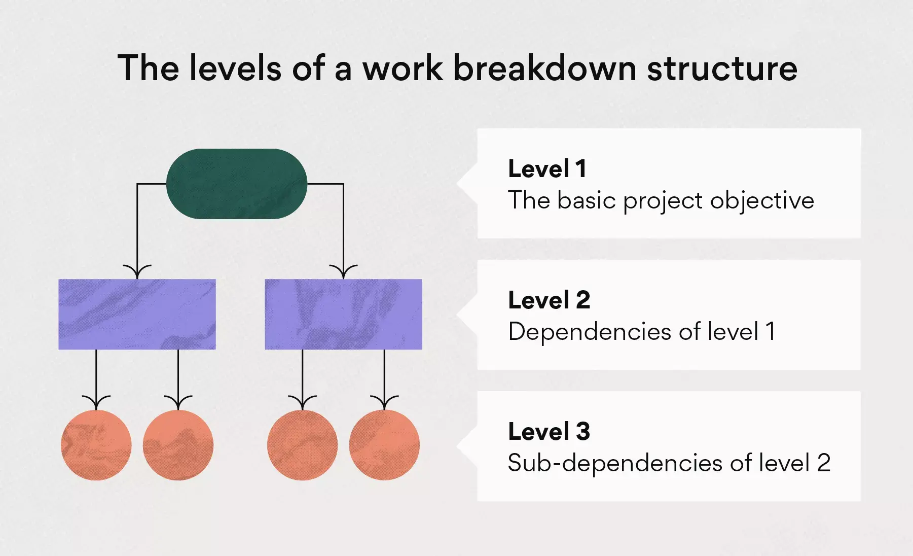
There are three main levels of dependencies, though your structure could require more or fewer than that. Each level is connected to a parent task, with the work needed to complete the parent task organized into dependencies.
Let’s take a look at the three highest level dependencies within a work breakdown structure.
Level 1: The parent task
The first level of a work breakdown structure is the most simplified form of the project since it contains the parent task. This is usually the same as the project objective .
Let’s say, for instance, that your project team is working on revamping your website design. The first level of your WBS might look something like this:
Launch new website design
As you can see, it’s simple and straightforward. Level one is the basic objective and the first step of your many project management phases . The work needed to complete this objective will come later in levels two and three.
Level 2: Dependencies and tasks
From there, your breakdown structure will get a bit more complicated depending on the scope of the project. Level two of your WBS will include subtasks, otherwise known as dependencies, of the parent task.
For example, let’s look at what tasks might be needed to launch a new website design.
Host a creative brainstorming session
Revamp brand guidelines
Create messaging framework
Redesign your logo
Add new photography
While slightly more granular than level one, level two is still a high-level overview of the dependencies needed to complete the project objective.
Level 3: Subtasks
In the third level of the WBS, break these dependencies down even further into more manageable components called sub-dependencies. At this stage—the lowest level of the project lifecycle—you’re defining the most detailed tasks. These actionable tasks will simplify the path to completing all your required deliverables.
Continuing the above example, here are the level three tasks you could use for a new site design:
Choose brand colors
Build a brand mood board
Assign UX designers
Build a mockup design
Review and approve mockups
Schedule a brand photoshoot
Resize and edit pictures
As you can see, the work needed to complete the project objective is becoming much more clear. You may even choose to add additional levels to your WBS, depending on how specific you want your visual to be.
What’s included in a work breakdown structure?
A work breakdown structure is essentially a condensed project plan organized in a visual hierarchy. That means it contains everything that a successful project charter has, which includes WBS elements such as objectives, deliverables, timelines, and key stakeholders.
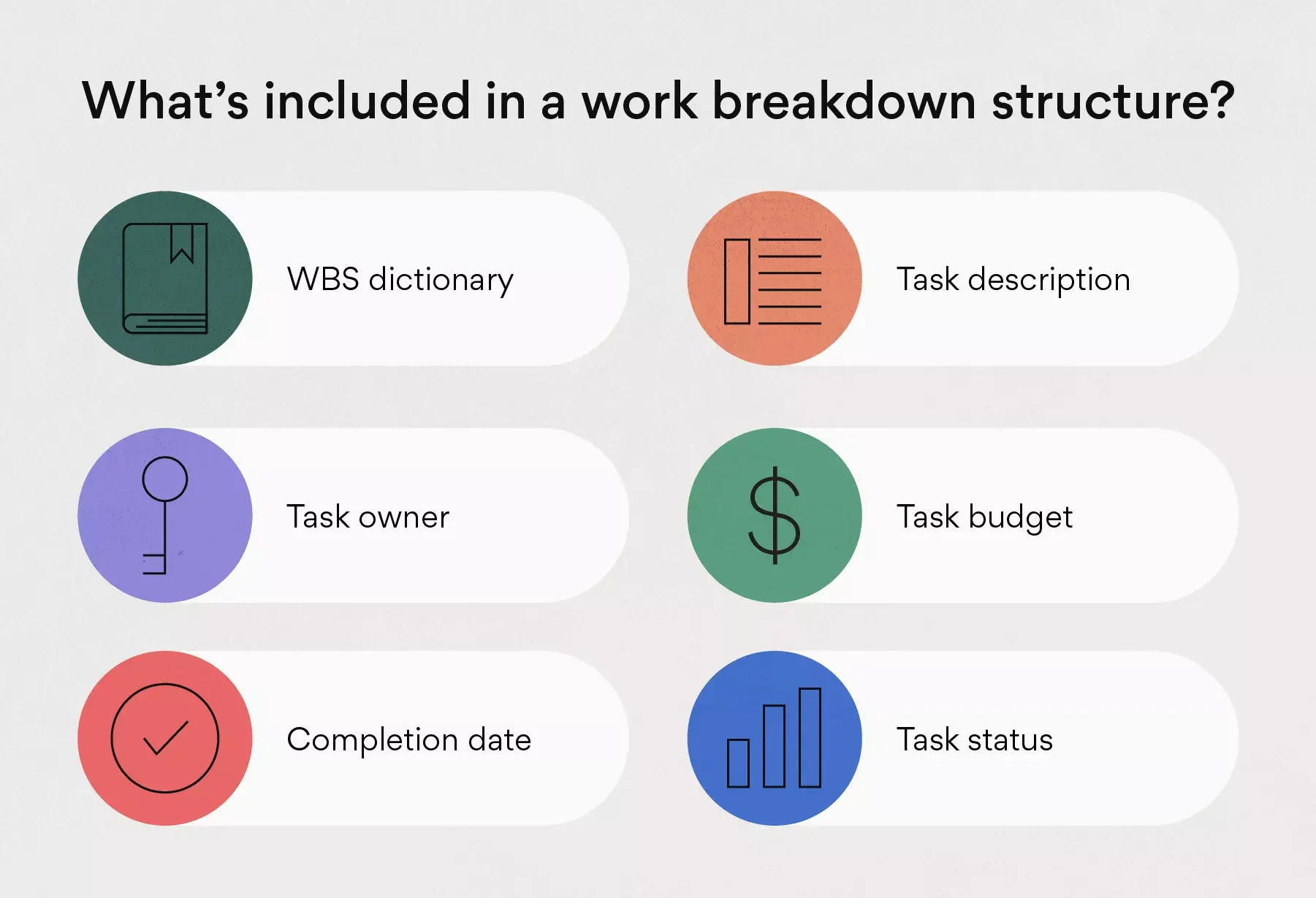
To create your own breakdown structure, you first need to know what to put in one. Thankfully, we’ve got you covered. Let’s take a look at some of the key pieces to include in your work breakdown structure.
WBS dictionary
A work breakdown structure dictionary is a great place to start when building a new project structure. Because the visual nature of a good WBS doesn’t allow room for detailed explanations, the WBS dictionary describes each task in more detail. Creating a dictionary is an instrumental part of helping project team members more easily find necessary details of your tasks.
While created by you, it may be beneficial to enlist the help of team members from various departments. This will ensure the dictionary is as useful as possible and all items are explained correctly.
Some fields you should include in your dictionary are:
Task names: Keep this clear and simple, a few words at most.
Descriptions: Go into a little more detail but no more than a sentence or two.
Deliverables : Again, specificity is your friend here. Be clear about what, exactly, you’re expecting the team to complete.
Budget : your projected expenses, including how much you’ll spend, for what, and by when.
Milestones : Significant moments on the project timeline where a batch of tasks are completed.
Approvals: What tasks—if any—need approvals.
While there are multiple fields you can include, the main thing to consider is creating a resource where project team members can find information on the project work needed to complete various tasks.
Task description
The task descriptions include both a task name and a brief description of the objectives. Since your WBS won’t have space for a full description, you can include additional details in your WBS dictionary.
The objective of the task description is for team members to easily recognize what the task is in the shortest way possible. So don’t get too caught up in the level of detail needed just yet.
The assigned task owner is an important piece to include both for accountability reasons and for communication. The easier it is to find answers, the quicker the tasks will be finished. While project managers are often task owners, department heads, and managers may also be owners depending on the type of task.
There’s nothing worse than wasting time looking for project information. Assigning task owners can improve team productivity as project stakeholders will be able to quickly direct questions to the appropriate person.
Task budget
While not always needed, projects that require large budgets should be tracked carefully. It’s helpful to assign specific task budget caps in order to easily track how close you are to your allocated budget.
Not tracking your budget could result in spending more than anticipated, which can dig into your profit margin. So be sure to not only track your total budget but individual task costs as well.
Completion date
It shouldn’t be a shock to hear that tracking your target completion date is a rather important detail. That said, it’s important to be prepared for changes to your completion date.
While it can be difficult to manage multiple projects that go over their allotted timeline, sometimes it’s inevitable. In order to properly track progress, you should break down each task in a timeline or other project management tool . This way you can catch timeline delays in real time and work to prevent deadline issues from stacking up and causing you to miss your original completion date.
Task status
Along with timeline tracking, documenting task status is important for quick progress checks. This can be logged in a few different ways, but many teams use terms such as open, in progress, and complete.
This will not only help track progress but give a high-level overview of team productivity. For example, if there’s a pattern of select teams unable to complete tasks there may be an underlying issue. That way you can work to solve team workload or communication issues before they become huge problems.
How to create a work breakdown structure
Now comes the fun part. Since a work breakdown structure is in the form of a visual hierarchy, there are a number of ways to create yours. The best part is that you get to pick which method is right for you and your team.
Common visual methods that teams use include timelines, Kanban boards , and calendars. Depending on the software you use, some features may look slightly different in each. Let’s dive into these three methods in order to provide a deeper understanding of how you can create a work breakdown structure in each.
Timelines (or Gantt charts)
Timelines are great tools to visualize work in a fun and colorful way. They’re also great at providing the necessary functionality for a WBS. Here are some of the functions you get using a timeline, also known as a flowchart or Gantt chart :
Import traditional spreadsheets
Track progress
Adjust tasks
Connect tasks by dependencies
Adjust deadline shifts
Assign task owners
Store unscheduled tasks
Adjust color tracking
Section by levels
Filter and sort tasks
You can start your WBS in a number of ways, including by importing an existing spreadsheet or building it directly in timeline software . Timelines are different from Kanban boards and calendars due to the visual layout and adjustable functionality. It’s really up to your preference to determine which visual is right for your team.
![work breakdown structure research [Product ui] Gantt chart project, organized timeline view in Asana with dependencies and due dates (Timeline)](https://assets.asana.biz/transform/aa091ca9-b87c-4fb0-96ad-47453f5473df/inline-project-management-gantt-chart-basics-2-2x?io=transform:fill,width:2560&format=webp)
Kanban boards
Kanban boards are similar to timelines but differ in the way they’re visually organized. Instead of being organized in a horizontal line, they’re designed to look like boards. Kanban software can help with the following to keep your projects on track:
Plot workflows
Communicate in one place
Plan product roadmaps
A Kanban board is another great option for building out your WBS, and it’s one of the most frequently used tools for day-to-day resource management needs. One of the best things about this tool is that you can see task details up front. This makes it a great option if you’re unable to create a WBS dictionary.
The best way to get started with this method is to start building your hierarchy within your Kanban board.
The third option for creating a WBS of your own is by using team calendar software . While not as commonly used for breakdown structures as the previous options, they’re a great tool to visualize projects. They’re also especially helpful for switching between day, week, and month views for large projects.
Calendars are great tools for creating a WBS and they give you a different visual experience from the options above. To start your structure using a calendar, you can import an existing spreadsheet or start building a new project within your calendar software.
Work breakdown structure example
Now that you know what goes into a WBS and how to build one using a variety of software tools, let’s look at a tangible WBS example. While your template will look slightly different depending on the method you use to create it, your WBS should include similar task hierarchies and levels.
Here is an example work breakdown structure to get you started on your own.
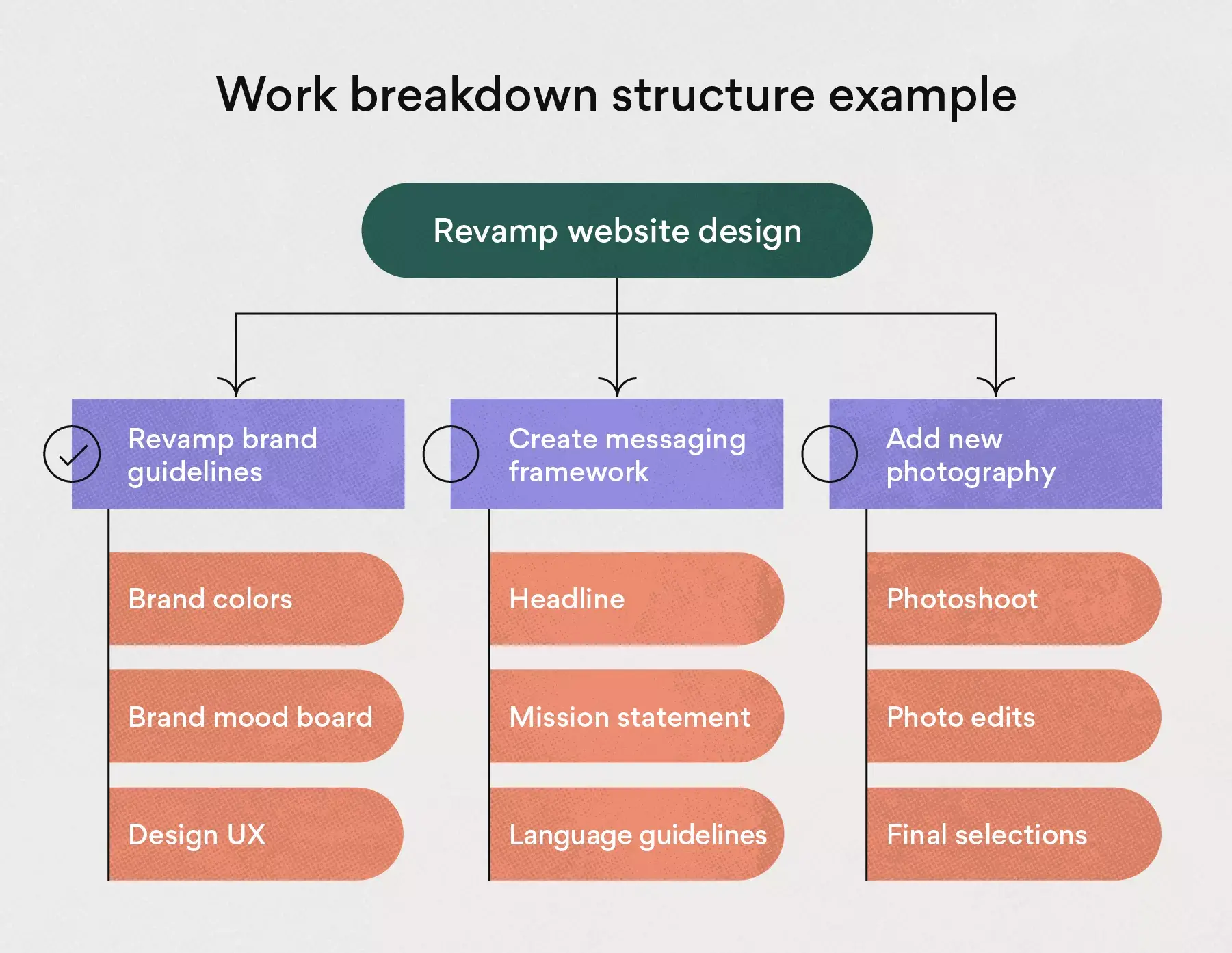
Here is an example work breakdown structure from the above details to get you started on your own.
WBS name : Website design
Description : Revamp our old website design based on the new branding.
Completion date : 9/15/21
Budget : $50,000
Revamp website design
Revamp brand guidelines (Complete)
Create messaging framework (Complete)
Redesign logo (In progress)
Add new photography (Open)
1. Revamp brand guidelines
Brand colors—Kat Mooney
Brand mood board—Kat Mooney
Design UX—Ray Brooks
2. Create messaging framework
Headline—Daniela Vargas
Mission statement—Daniela Vargas
Language guidelines—Daniela Vargas
3. Redesign logo
Sketch—Kabir Madan
Mockups—Kat Mooney
Final designs—Kat Mooney
4. Add new photography
Photoshoot—Kabir Madan
Photo edits —Kat Mooney
Final selections—Kabir Madan
Remember that your WBS will look different based on the size of the project, its complexity, the timeline, and your chosen software. Each of these details will shape the dependencies and visual hierarchy of your project.
Make your work breakdown structure work for you
When it comes down to it, a work breakdown structure isn’t so hard to create. In fact, once you get the hang of it, you and your team can only benefit from adding a visual hierarchy or project tasks. Whether you’re a visual or verbal learner, there’s a work management tool out there for everyone.
With Asana, you can easily switch between lists, timelines, boards, and calendars without missing a beat. Less time spent on work about work ? Yes, please.
Related resources

Everything you need to know about requirements management

Gartner® Magic Quadrant™ for Adaptive Project Management and Reporting

How Asana drives impactful product launches in 3 steps

Waterfall, Agile, Kanban, and Scrum: What’s the difference?
| You might be using an unsupported or outdated browser. To get the best possible experience please use the latest version of Chrome, Firefox, Safari, or Microsoft Edge to view this website. |
Work Breakdown Structure (WBS) In Project Management

Updated: May 28, 2024, 12:42pm

A work breakdown structure (WBS) is a project management tool that takes a step-by-step approach to complete large projects with several moving pieces. By breaking down the project into smaller components, a WBS can integrate scope, cost and deliverables into a single tool. While most WBSes are deliverable-based, they can also be phase-based. Read on to learn more about what a WBS can do for your business.
Featured Partners
From $8 monthly per user
Zoom, LinkedIn, Adobe, Salesforce and more

On monday.com's Website
Yes, for unlimited members
$7 per month
Slack, Microsoft Outlook, HubSpot, Salesforce, Timely, Google Drive and more

On ClickUp's Website
$9.80 per user per month
Salesforce, Adobe, Miro, Netsuite, Quickbooks, SAP

On Wrike's Website
Yes, for one user and two editors
$9 per user per month
Google Drive, Slack, Tableau, Miro, Zapier and more

On Smartsheet's Website
What is Work Breakdown Structure?
The Project Management Institute’s PMBOK® Guide—Third Edition defines WBS as “a deliverable-oriented hierarchical decomposition of the work to be executed by the project team to accomplish the project objectives and create the required deliverables. It organizes and defines the total scope of the project. Each descending level represents an increasingly detailed definition of the project work. The WBS is decomposed into work packages. The deliverable orientation of the hierarchy includes both internal and external deliverables.”
Some commonly used terms used with WBS project management include:
- Acceptance criteria: Standards to be met to achieve customer or other stakeholder requirements
- Budget: Expenses associated with the project, which can be broken down by deliverables or phases
- Deliverables: The product, service or results created at various stages of the project. For instance, in a website design project, a deliverable-based WBS would be structured around deliverables such as URL, layout and written content
- Milestones: Critical stages of the project identified in the WBS
- Phases: The various stages of a project. For instance, in a website design project, a phase-based WBS would be structured around things like discovery, design and launch, rather than specific deliverables
- WBS: Work breakdown structure
Key Characteristics and Components of the WBS
A key component of a work breakdown structure is the 100% rule. This means that the WBS encompasses all aspects of the project, as well as the person or team responsible for that component.
Another key characteristic of WBS is its leveled structure. When applying the 100% rule, Level 1 of the WBS will be the totality of the project. Some WBSs include a description or overview of the project at the top level if it isn’t self-explanatory. Then each level below breaks down the project into further detail, using the 100% rule at each level. For instance,if you’re creating a WBS for a new website, Level 1 would be “ Website for New Brand”. Level 2 elements break down the deliverables necessary to bring the project to completion, such as secure website url, design layout and develop content. Each subsequent level continues breaking down the elements into further detail.
Why a WBS Is Helpful for Project Management
Work breakdown structure is a helpful project management tool for several reasons. First, it breaks down the project into bite-size components, making the project less overwhelming and more manageable.
Second, it provides a roadmap for the different individuals and teams working on the project. Many projects involve different teams moving in tandem, all of which need to coordinate and integrate for project completion. By using a WBS, the various individuals and teams can focus on their specific tasks and deliverables while also seeing how their piece fits into the project as a whole.
Finally, a WBS is an excellent tool for measuring project completion, identifying milestones and allocating budget resources. By using the 100% rule, project managers can be confident that the project is properly budgeted and that they won’t run into any roadblocks due to a “surprise” deliverable.
How To Create and Use a WBS Effectively
To use a work breakdown structure effectively, it is important to include all components of a project (remember that 100% rule described above) but without too much detail. Turns out, there can be too much of a good thing when it comes to the WBS.
To create a WBS:
1. Define the project. The first step in creating a work breakdown structure is to clearly establish the project. For some projects, this might be fairly straightforward. For other projects, it might require refining the actual scope of the project so that the WBS is scaled appropriately and doesn’t become unwieldy.
2. Set project boundaries. Once the project is defined and described, you can set boundaries on what is and isn’t included in the WBS.
3. Identify project deliverables. This will include high-level deliverables associated with the project, such as a Project Scope Statement or Mission Statement.
4. Define Level 1 elements. Remember the 100% rule while creating the Level 1 deliverables.
5. Break down each of the Level 1 elements. The process of breaking down Level 1 elements is called decomposition. It consists of breaking down a task into smaller and smaller pieces, applying the 100% rule at each level. At each subsequent level, ask yourself whether further decomposition would improve project management. Continue breaking down the elements until the answer to that question is “no.” When you’ve completed the decomposition process for each element in Level 1, the WBS is complete.
6. Identify team members. Identify an individual or team who is responsible for each element.
7. Create a Gantt chart to accompany the WBS. A Gantt chart shows activities over time so that you can visually see information related to the schedule of the project and its various activities.
WBS Examples, Templates, and Tools
If you’re looking for some guidance, there are many examples, templates and software tools out there to help you create a work breakdown structure for your project. If you want to see some examples of how others have used the WBS as a project management tool, check out WorkBreakdownStructure.com .

If you need a little more guidance, templates might be the way to go. There are several templates available to download on Monday , ProjectManager and Wrike .
If you’re looking for even more help with the creation of your WBS, or you need a more comprehensive and detailed WBS, a software tool might be the way to go. Platforms like WBS Schedule Pro and Microsoft Visio offer intuitive software options.
Frequently Asked Questions
What is meant by work breakdown structure.
Work breakdown structure takes a large project and, quite literally, breaks it down into smaller components. This makes it easier for teams to identify scope, cost and deliverables and delegate tasks to the team members who are best suited for the job.
Why should project managers use a WBS?
A work breakdown structure can help project managers “see the forest through the trees” by showing the individual components of a project in one document. It also helps project managers communicate information regarding a project budget and timeline to key stakeholders, including the individuals and teams involved in the project. Finally, by breaking down the project into smaller components, a WBS integrates scope, cost and deliverables into a single tool.
How can a project manager get started with a WBS?
There are several tools and software available to help you create a WBS. Monday , ProjectManager and Wrike all offer templates and tools to guide you in the process. Additionally, there are software options like WBS Schedule Pro and Microsoft Visio available if you need a more comprehensive approach.
Should you use a Gantt chart with WBS?
Many project managers do find that Gantt charts complement WBS well. They help teams to estimate the time frame of individual tasks and visualize the overall timeline of projects from start to finish.
- Best Project Management Software
- Best Construction Project Management Software
- Best Project Portfolio Management Software
- Best Gantt Chart Software
- Best Task Management Software
- Best Free Project Management Software
- Best Enterprise Project Management Software
- Best Kanban Software
- Best Scrum Software
- Best Agile Project Management Software
- Asana Review
- Trello Review
- monday.com Review
- Smartsheet Review
- Wrike Review
- Todoist Review
- Basecamp Review
- Confluence Review
- Airtable Review
- ClickUp Review
- Motion App Review
- Monday vs. Asana
- Clickup vs. Asana
- Asana vs. Trello
- Asana vs. Jira
- Trello vs. Jira
- Monday vs. Trello
- Clickup vs. Trello
- Asana vs. Wrike
- What Is Project Management
- Project Management Methodologies
- 10 Essential Project Management Skills
- SMART Goals: Ultimate Guide
- What is a Gantt Chart?
- What is a Kanban Board?
- What is a RACI Chart?
- What is Gap Analysis?
- Agile vs. Waterfall Methodology
- What is a Stakeholder Analysis
- What Is An OKR?

What Is SNMP? Simple Network Management Protocol Explained
What Is A Single-Member LLC? Definition, Pros And Cons
What Is Penetration Testing? Definition & Best Practices
What Is Network Access Control (NAC)?
What Is Network Segmentation?

How To Start A Business In Louisiana (2024 Guide)
Christine is a non-practicing attorney, freelance writer, and author. She has written legal and marketing content and communications for a wide range of law firms for more than 15 years. She has also written extensively on parenting and current events for the website Scary Mommy. She earned her J.D. and B.A. from University of Wisconsin–Madison, and she lives in the Chicago area with her family.
Cassie is a deputy editor collaborating with teams around the world while living in the beautiful hills of Kentucky. Focusing on bringing growth to small businesses, she is passionate about economic development and has held positions on the boards of directors of two non-profit organizations seeking to revitalize her former railroad town. Prior to joining the team at Forbes Advisor, Cassie was a content operations manager and copywriting manager.

IMAGES
VIDEO
COMMENTS
Abstract. Work Breakdown Structure (WBS) is a deliverable-oriented hierarchical decomposition of the work to be executed by the project team to accomplish the project objectives and create the ...
An effective work breakdown structure: Is a deliverable-oriented grouping of project elements. Is created by those doing the work. Contains 100% of the work defined by the scope or contract and captures all deliverables (Internal, External, Interim) in terms of work to be completed, including project management.
The work breakdown structure (WBS) is a graphic family tree that captures all of the work of a project in an organized way. A subsea field development project can be organized and comprehended in a visual manner by breaking the tasks into progressively smaller pieces until they are a collection of defined tasks, as shown in Figure 6-9. The costs of these tasks are clear and easy to estimate ...
2.2.3 Work Breakdown Structure Elements by Other Performing Entities 9 2.3 Development Guidelines 9 2.4 Summary 10 Chapter 3: WBS Development and Control 11 ... used for all types of NASA projects and work activities including research, development, construction, test and evaluation, and operations. The products of these work efforts may be
The Work Breakdown Structure (WBS) is a powerful tool for project management. It is the cornerstone of effective project planning, execution, controlling, statusing, and reporting. All the work ...
Understand and apply new concepts regarding Work Breakdown Structures The Work Breakdown Structure (WBS) has emerged as a foundational concept and tool in Project Management. It is an enabler that ensures clear definition and communication of project scope while performing a critical role as a monitoring and controlling tool. Created by the three experts who led the development of PMI®'s ...
Work breakdown structure (WBS) is a one "procedure, concept or technique" utilized for project planning and control. Thus the search term WBS was instrumental in this review of IJPM Original Research Articles published between 1983 and 2013. A simple numerical ranking protocol indicated WBS significance in 140 documents.
For general information on our other products and services please contact our Customer Care Department within the U.S. at (800)-762-2974, outside the U.S. at (317)-572-3993 or fax (317)-572-4002. Project Management Institute (www.pmi.org) is the leading advocate for the project management profession globally.
At the end of the chapter, the reader should be able to: • Describe the best practices for building a project schedule. • Understand the concept of using an organizing principle for developing the work breakdown structure. • Describe the types of task dependencies. • Define the critical path and understand why it is important to project ...
Summary This chapter contains sections titled: Introduction Communication—Users of the WBS System Integration—Using the WBS WBS—Responsibility Relationship WBS Development Examples of a WBS Conclusions
THE WBS. Work Breakdown Structure (WBS): a product-oriented "family tree" of project components that organizes and defines the total scope of the project. Each descending level represents an increasingly detailed definition of a project component. Project components may be products or services [1].
Specifically, the Planning Process Group begins with three essential steps: scope planning (3.2.2.2), scope definition (3.2.2.3) and work breakdown structure development (3.2.2.4) (PMI, 2004). The following discussion will examine the current trends and practice regarding work breakdown structures.
Scope management allows project managers to react when a project underperforms regarding schedule, budget, and/or quality at the execution stage. Scope management can also minimize project changes and budget omissions, as well as improve the accuracy of project cost estimates and risk responses. For scope management to be effective, though, it needs to rely on a robust work breakdown structure ...
A work breakdown structure (WBS) is a visual, hierarchical and deliverable-oriented deconstruction of a project. It is a helpful diagram for project managers because it allows them to break down their project scope and visualize all the tasks required to complete their projects. All the steps of project work are outlined in the work breakdown ...
Impact of various work-bre~~ow~ structures on project conceptualization: S Globerson. curriculum, and is unable to handle many subordinates. simultaneously, the project is bound to fail. The ...
A work breakdown structure provides a clear and comprehensive overview of the project, allowing you to monitor progress, identify potential issues, and make necessary adjustments as issues arise. By breaking the project down into smaller pieces, you can track progress more easily and keep everyone on the same page. 4. Enhanced communication.
Work breakdown structures (WBS) are a fundamental building block of practicing project management. This tool helps project managers initiate and implement the planning process in conjunction with the many other essential project management processes, such as estimating, scheduling, and controlling. And yet, despite the benefits derived from an effective WBS, research suggests that project ...
Example of a work breakdown structure for opening a restaurant. This type of a work breakdown structure will help you to track processes to eliminate unnecessary activities and expenses. The main activities will relate to marketing research, design, construction, installation, resource management, advertisement necessary equipment, etc.
A WBS in project management is a hierarchical decomposition of a project into smaller components. It starts with the overall project goal at the top and then breaks things down into smaller, more efficient deliverables. Each level of a work breakdown structure provides more detailed descriptions of project work, starting from the high level ...
A work breakdown structure (WBS) is a visual project breakdown. Beginning with the scope of work, the WBS shows the deliverables and how they connect back to the overarching project. Since a work breakdown structure is displayed visually, it can be created using a combination of workflow management software and project management frameworks.
Getty. A work breakdown structure (WBS) is a project management tool that takes a step-by-step approach to complete large projects with several moving pieces. By breaking down the project into ...
WBS (Work Breakdown Structure) plays an important role in every construction project. WBS is a hierarchy of decreasing scope of work to become the smallest level called a work package, making it ...